
Coating method for an end winding of an electric motor

An end winding and coating technology, which is applied in the direction of coating, electric components, manufacturing winding connectors, etc., can solve the problems of complex geometric structure, small layer thickness, uneven coating thickness, etc., and achieve material consumption saving , Improve the conveying rate and save the effect of coating material

Inactive Publication Date: 2008-04-02
SIEMENS AG
View PDF0 Cites 3 Cited by
  • Summary
  • Abstract
  • Description
  • Claims
  • Application Information

AI Technical Summary

Problems solved by technology

Due to the sometimes complex geometry of the end windings, the layer thicknesses of the coatings produced by these known end winding coating methods are not uniform
Especially in corners, points, crevices, blind spots or shaded areas, often only small layer thicknesses can be achieved

Method used


Image

  • Coating method for an end winding of an electric motor
  • Coating method for an end winding of an electric motor

Examples


Embodiment Construction

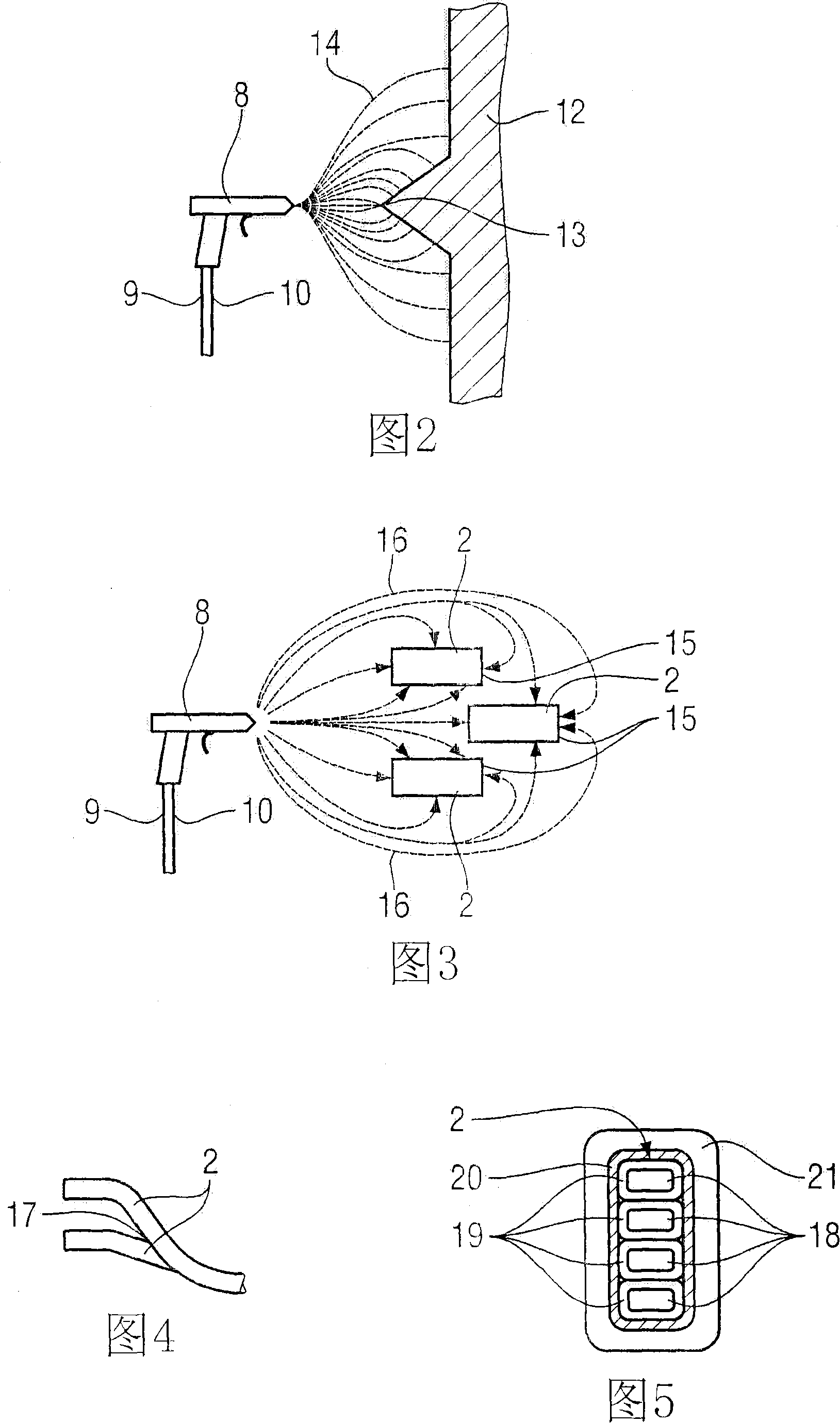
[0023] The same components are denoted by the same reference symbols in FIGS. 1 to 5 .

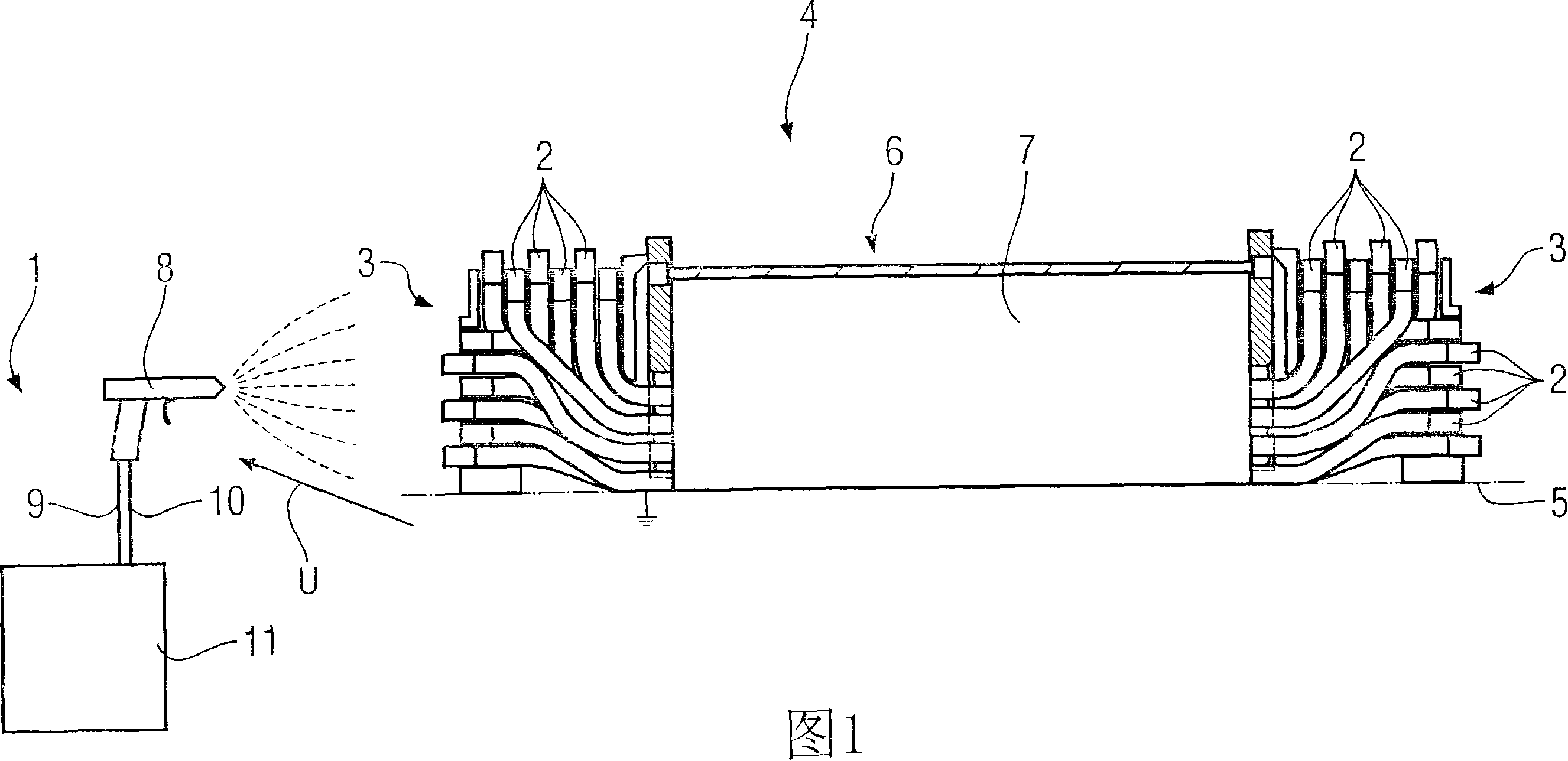
[0024] What Fig. 1 shows is the embodiment of a spraying device 1, and described spraying device is used for carrying out electrostatic spraying to two end windings 3 that are made up of a plurality of wires 2 of a motor 4, wherein, motor 4 is shown in Fig. 1 Appears in partial cross-section.

[0025] The sectional view of the motor 4 is in fact a sectional view of a stator 6 of the motor 4 taken along the axis of rotation 5 , but only the upper half of the stator 6 is shown. FIG. 1 does not show the area 7 with the stator laminations and the coil wires embedded in the slots in detail, but only shows this actually active area in schematic form. The end windings 3 are arranged on both axial end faces of the active area 7 and consist of a large number of wires 2 drawn out from the stator iron laminations in the direction of the rotation axis 5 . The end winding 3 , in particular the wiring...


PUM


Abstract

The coating method is for application to the coating of an end winding (3) of an electric motor (4), whereby the end winding (3) comprises several conductor arrangements (2) for coating. The coating material for application is atomised by means of a spray device (1). An electrostatic potential difference (U) is applied between the spray device (1) and the conductor arrangements (2) for spraying, such that atomised particles of the coating material are transported along the forming electrical field lines in the direction of the conductor arrangements (2) of the end windings (3) for coating.

Description

technical field [0001] The invention relates to a coating method suitable for an end winding of an electric machine, wherein the end winding includes a plurality of wires to be coated. Background technique [0002] Electrical machines, such as electric motors or generators, have end windings provided with coatings for various purposes. These coatings are prepared by impregnating resins and impregnating varnishes after multiple impregnations, or cast with inorganic impregnating resins (casting resins), and have the functions of electrical insulation, mechanical protection or chemical protection. Processes used therein are, for example, dipping or airless spraying. Due to the sometimes complex geometry of the end windings, the layer thicknesses of the coatings produced by these known end winding coating methods are not uniform. Especially in corners, points, crevices, blind spots or shaded areas, often only small layer thicknesses can be achieved. Contents of the invention...

Claims


Application Information

Patent Timeline
Patent Type & Authority Applications(China)
IPC IPC(8): H02K15/12B05D1/04
CPCB05D1/04H02K15/0056H02K15/12
Inventor 马丁·考夫霍尔德伯恩哈德·克劳斯纳
Owner SIEMENS AG
Learn More