

Apparatus and method for processing elevator wire rope groove
A groove processing and steel cable technology, which is applied in metal processing equipment, elevators in buildings, grinding/polishing safety devices, etc. Reducing the frequency of tool replacement, preventing the deterioration of processing accuracy, and preventing the reduction of service quality are achieved without considering problems such as refurbishment
- Summary
- Abstract
- Description
- Claims
- Application Information
AI Technical Summary
Problems solved by technology
Method used
Image

Examples
Embodiment approach 1
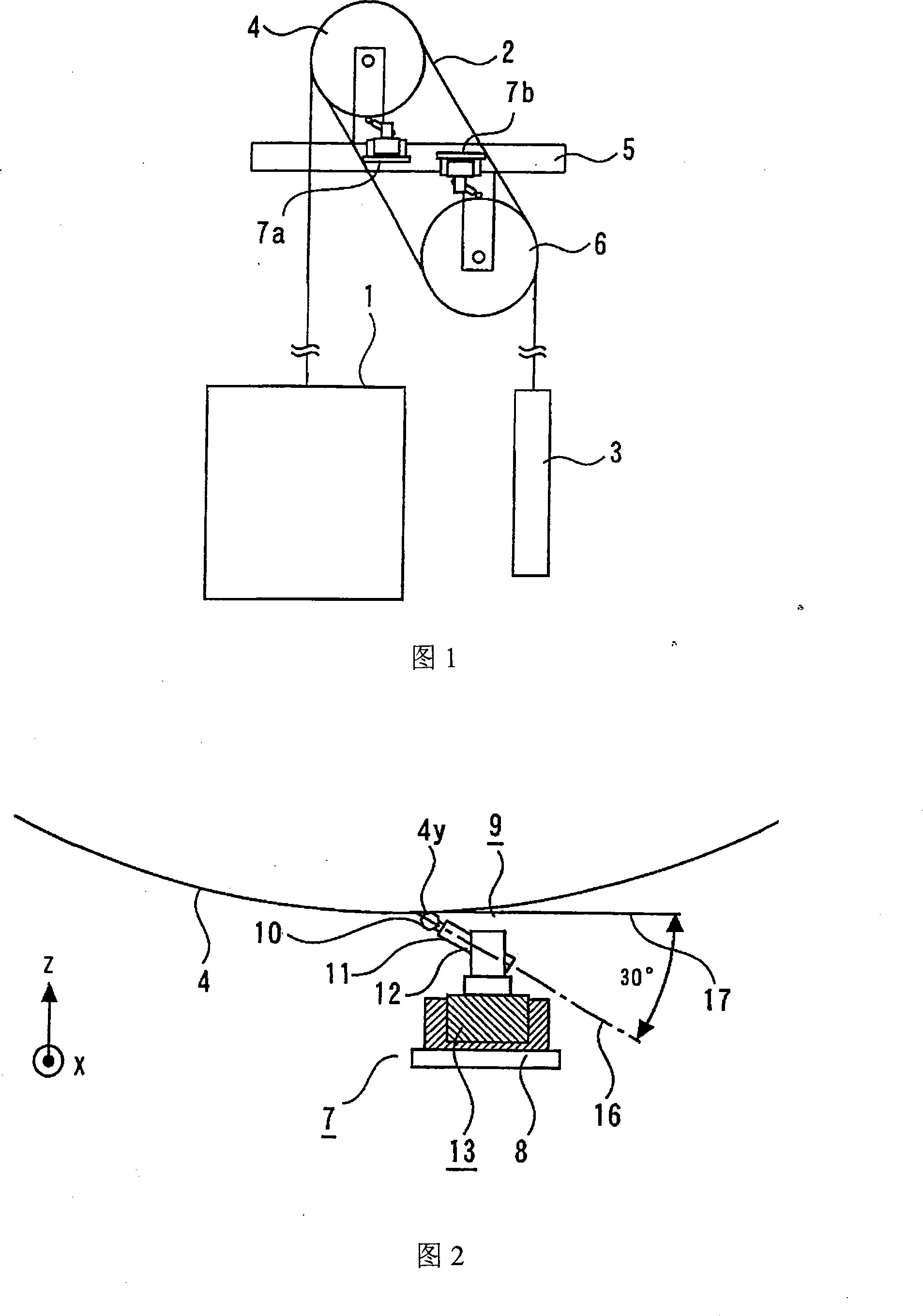
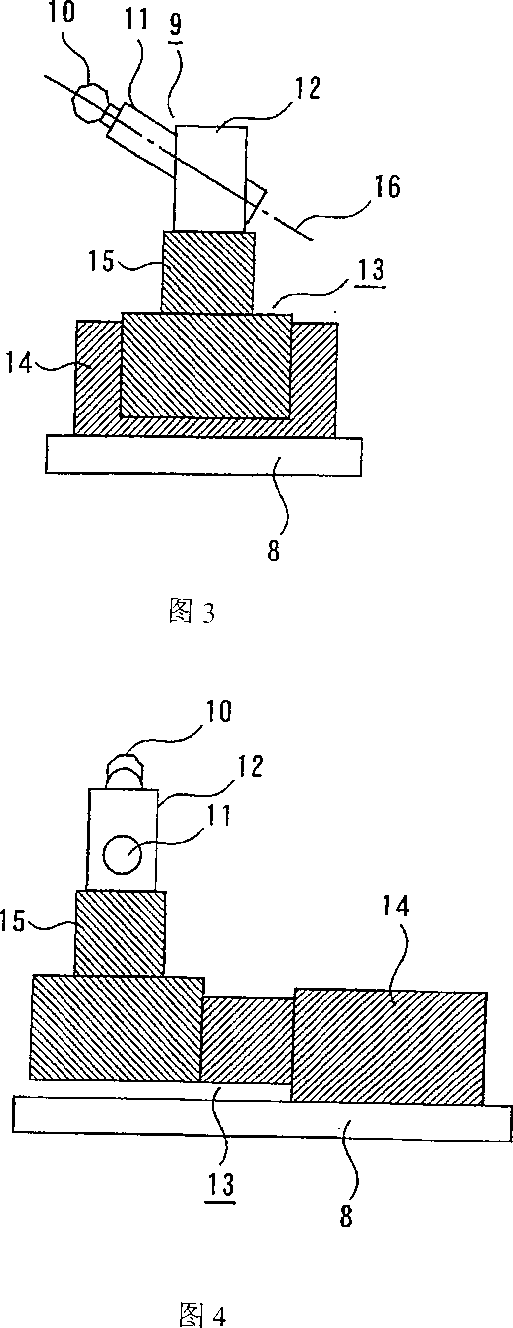
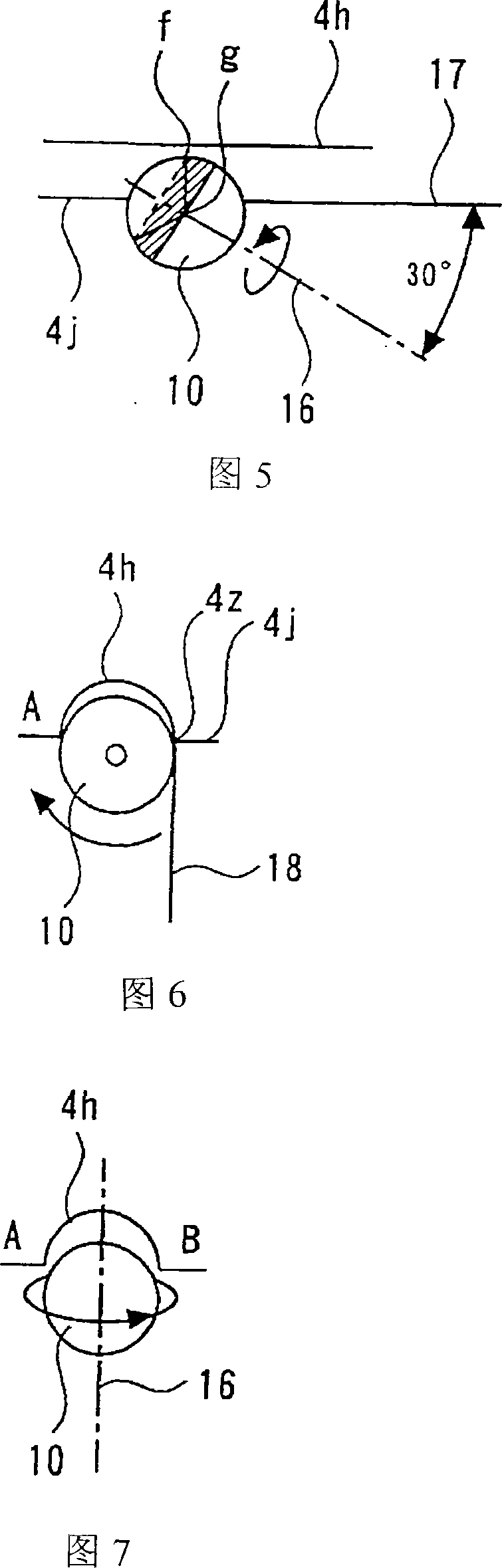
[0073] Fig. 1 is a schematic configuration diagram of an elevator device in a state where an elevator cable groove processing device according to Embodiment 1 of the present invention is installed; Side view; FIG. 3 is a side view for explaining the movable state of the movable support part of the cable groove processing device in Embodiment 1 of the present invention; FIG. The rear view of the movable state of the movable support part of the cable groove processing device; Figure 5 is a side view when the angle between the rotation axis of the processing part and the tangent line at the processing point on the drive cable pulley is 30 degrees; Figure 5 6 is the front view when the angle between the axis of rotation of the processing part and the processing point on the driving cable pulley is 30 degrees; Figure 7 is the angle between the axis of rotation of the processing part and the processing point on the driving cable pulley The side view when the tangent angle is 90 degr...
Embodiment approach 2
[0094] Fig. 8 is a side view of the elevator cable groove processing device in Embodiment 2 of the present invention, Fig. 9 is a front view of the cable groove processing device in Embodiment 2 of the present invention, and Fig. 10 is Embodiment 2 of the present invention The rear view of the cable groove processing device in FIG. 11 is a flow chart showing the steps of controlling the feed amount according to the position measurement value of the elevator cable groove processing device in Embodiment 2 of the present invention. FIG. Figure 13 is a flow chart showing the steps of controlling the feed rate according to the load measurement value. In the figure, the same or equivalent parts as those in Embodiment 1 are given the same reference numerals, and description thereof will be omitted.
[0095] In Embodiment 2, the processing efficiency of the cable groove processing device according to Embodiment 1 is further improved, and the dust collection port 19 of the dust collect...
PUM
 Abstract
Description
Claims
Application Information