
Dielectric materials high-temperature complex dielectric constant measurement method based on terminal short circuit method

A technology of complex permittivity and terminal short-circuit method, applied in microwave and millimeter wave fields, can solve the problems of large test error, increase of complex permittivity test error, inability to accurately measure the size of the test waveguide section and microwave loss, etc.

Inactive Publication Date: 2008-04-09
UNIV OF ELECTRONICS SCI & TECH OF CHINA
View PDF0 Cites 59 Cited by
  • Summary
  • Abstract
  • Description
  • Claims
  • Application Information

AI Technical Summary

Problems solved by technology

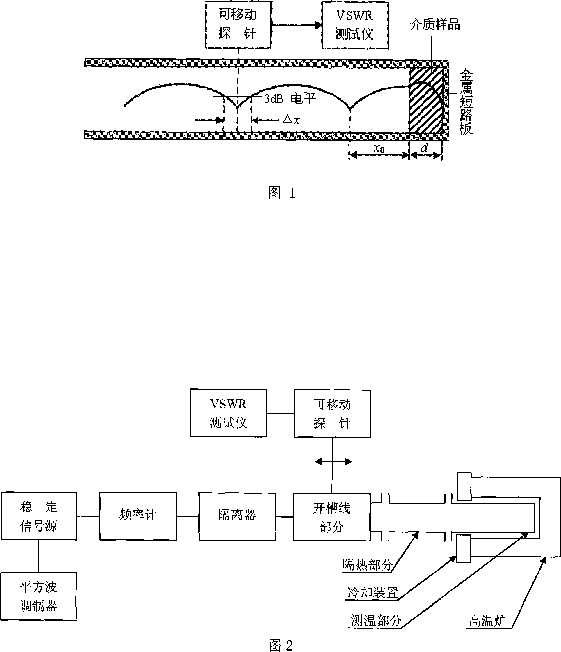
When using the 3dB bandwidth at the minimum point of the standing wave to solve the microwave loss of the waveguide, the larger the standing wave ratio is, the more likely the minimum electric field value sampled and measured by the probe will be interfered by the leakage field, background noise, etc., resulting in greater test error
[0029] To sum up, at home and abroad, the use of terminal short-circuit method to test the electrical parameters of dielectric materials has been studied for many years. When calculating the size of the test waveguide section and measuring the microwave loss of the waveguide section, there are large errors.
[0030] As far as the inventors know, in the existing high-temperature testing method for electrical parameters of materials using the terminal short-circuit method, the size and microwave loss of the test waveguide section cannot be accurately measured, resulting in an increase in the test error of the complex permittivity

Method used


Image

  • Dielectric materials high-temperature complex dielectric constant measurement method based on terminal short circuit method
  • Dielectric materials high-temperature complex dielectric constant measurement method based on terminal short circuit method
  • Dielectric materials high-temperature complex dielectric constant measurement method based on terminal short circuit method

Examples


Embodiment Construction

[0073] The technical content of the present invention describes in detail a method for measuring the high-temperature complex permittivity of dielectric materials based on the terminal short-circuit method. For the convenience of analysis and calculation, the test waveguide of the built test system adopts a rectangular waveguide. For the case where the test waveguide is a cylindrical waveguide or a ridge waveguide, or even a coaxial transmission line, the idea of ​​the present invention is still used, but the specific calculation process is different. Various specific real-time methods formed by using test waveguides of different shapes can also achieve the effects described in the present invention.


PUM


Abstract

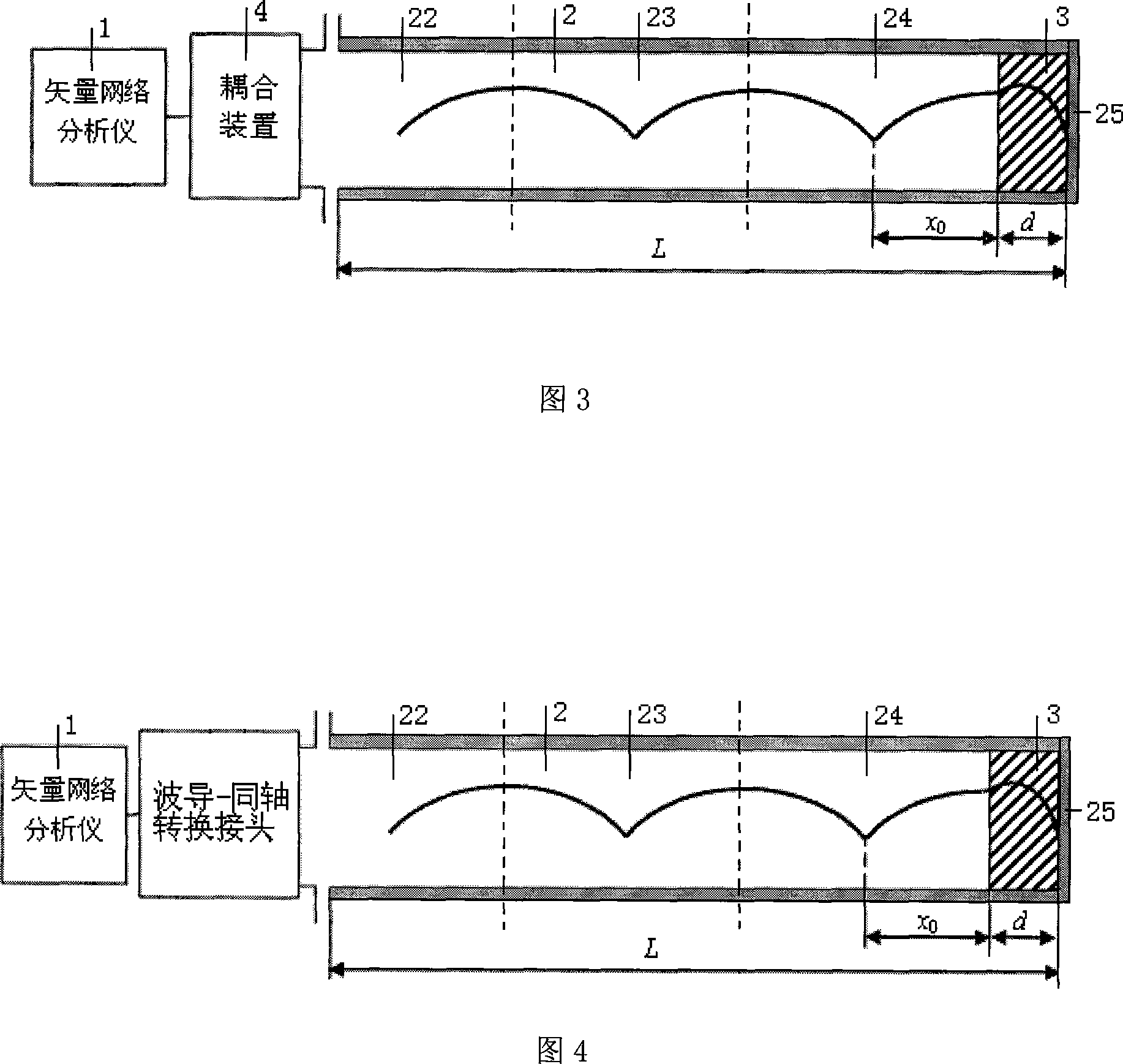
The present invention provides a medium material high-temperature complex permittivity measurement method based on terminal short circuit and pertains to technology of microwave and millimeter wave dielectric material complex permittivity measurement. When the present invention adopts the terminal short circuit for measurement of high-temperature medium material complex permittivity, a heat dissipation wave guide, a heat insulation waveguide, a high-temperature waveguide with a certain length, and a coupling device, a short circuit board are together constitute a reactive type resonator, and dimensions and microwave loss of the resonator under different temperature can be obtained by measurement of resonance frequency and quality factor of the resonator, and the complex permittivity of the medium material under the temperature can be further measured. The present invention is suitable for the measurement of the medium material high-temperature complex permittivity of various frequency band based on the terminal short circuit, and meanwhile the present invention can measure the dimension and the microwave loss of the waveguide resonator under different temperature. As the present invention considers the changing of the dimension and the microwave loss of the waveguide resonator caused by the influence of the temperature, the present invention has higher measurement accuracy and smaller error.

Description

Technical field [0001] The invention belongs to the technical field of microwaves and millimeter waves, and particularly relates to the complex permittivity test technology of microwave and millimeter wave dielectric materials. Background technique [0002] Microwave and millimeter wave dielectric materials are widely used in microwave and millimeter wave devices and systems. The research and application of dielectric materials and their performance evaluation must pass the actual test of their performance parameters. The complex dielectric constant is a basic parameter of microwave and millimeter wave media. They are the main basis for evaluating the microwave performance of dielectric materials and are also important parameters for the design of microwave devices. The terminal short-circuit method has the advantages of simple test fixture, wide test frequency range, small sample size, etc. It is commonly used to test the complex permittivity of microwave and millimeter wave die...

Claims


Application Information

Patent Timeline
IPC IPC(8): G01R27/26G01R31/00H01P7/00
Inventor 李恩李仲平聂在平何凤梅郭高凤张大海张其劭王金明
Owner UNIV OF ELECTRONICS SCI & TECH OF CHINA
Learn More