Servo loop circuit

A technology of servo loops and circuits, applied in the field of servo loops, can solve problems such as redundant DC offsets, and achieve the effect of eliminating DC offsets

Inactive Publication Date: 2008-04-09
MEDIATEK INC
View PDF0 Cites 4 Cited by
  • Summary
  • Abstract
  • Description
  • Claims
  • Application Information

AI Technical Summary

Problems solved by technology

[0008] However, the discontinuous switching of resistor values ​​results in an unwanted DC offset, which will be further explained later

Method used


Image

  • Servo loop circuit
  • Servo loop circuit
  • Servo loop circuit

Examples


Embodiment Construction

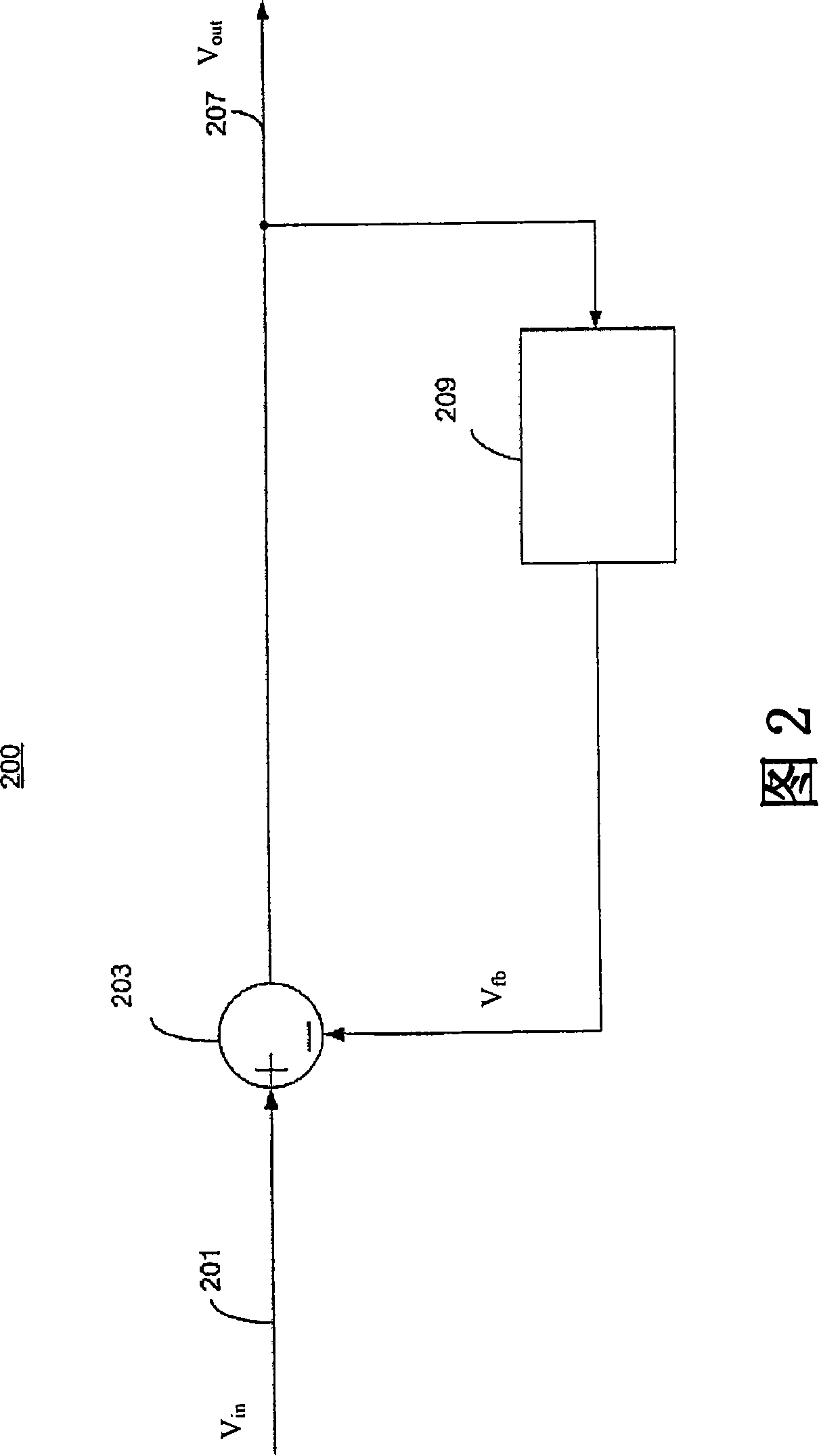
[0023] FIG. 2 is a schematic diagram of a servo loop circuit 200 according to an embodiment of the invention. The servo loop circuit 200 is used to remove low frequency signal components (eg, DC offset on direct conversion receivers). The servo loop circuit 200 has a signal path with an input port 201 for inputting an input signal V in , and the output port 207 is used to output the output signal V out sent to the next stage. The servo loop circuit 200 further includes a low-pass filtering device 209 . output signal V out is fed back to the low-pass filtering device 209, so only low-frequency signal components (such as DC offset) may pass through. Feedback low frequency signal component V fb (for example: feedback DC offset) from the input signal V through the subtractor 203 in Subtract from , to remove the DC offset therein.

[0024] The low-pass filtering means 209 can be implemented in any suitable technique, such as a conventional low-pass filter or an integrator. ...


PUM


Abstract

A servo loop circuit suitable for DC offset cancellation in a direct conversion receiver. The servo loop in accordance with the present invention has a low pass filtering device with a smoothly and continuously changed corner frequency, so that the response time of the low pass filtering device can be limited to a short period of time without inducing in additional DC offset. The smoothly and continuously changing of the corner frequency is performed by providing a continuously variable resistance by at least one continuously variable resistive unit, which may be implemented by transistor technique. The resistance of the continuously variable resistive unit is continuously varied by smoothly controlling the level of a voltage signal applied thereto. Thus the corner frequency response time can be limited and the extra DC offset is not admitted.

Description

technical field [0001] The present invention relates to a servo loop for removing a DC offset in a receiver, and more particularly to a servo loop circuit including a low-pass filtering device. Background technique [0002] A direct conversion receiver (Direct Conversion Receiver, DCR) receives a radio frequency signal and down-converts it into a base frequency signal through a mixer. The mixer utilizes a local oscillator signal provided by a local oscillator (LO) whose operating frequency is close to the radio frequency to down-convert the radio frequency signal. [0003] Figure 1 is a schematic diagram of a simple structure of a direct conversion receiver. As shown in the figure, the received radio frequency signal is amplified by a variable gain amplifier (variable gain amplifier, VGA) 110, and then down-converted to a base frequency by a local oscillator signal provided by a local oscillator 120 through a mixer 125 Signal. Next, the baseband signal is filtered by a lo...

Claims


Application Information

Patent Timeline
Patent Type & Authority Applications(China)
IPC IPC(8): H04L25/06H04L25/02H04B1/10
CPCH04B1/30
Inventor 钟元鸿
Owner MEDIATEK INC
Why Eureka
Try Eureka