Multi-hop relay method and multi-hop relay system

A technology of multi-hop relay and relay station, applied in the field of relay, can solve the problems of not being able to more effectively improve BS coverage, no transmission format definition, inability to realize multi-hop relay, etc., to speed up the process of resource allocation and adjustment, The effect of ensuring reliability and improving reliability

Inactive Publication Date: 2008-04-23
蔡永梅
View PDF0 Cites 84 Cited by
  • Summary
  • Abstract
  • Description
  • Claims
  • Application Information

AI Technical Summary

Problems solved by technology

[0008] However, the existing relay system only provides base station frames and terminal frames, without the definition of transmission forma

Method used


Image

  • Multi-hop relay method and multi-hop relay system
  • Multi-hop relay method and multi-hop relay system
  • Multi-hop relay method and multi-hop relay system

Examples


Embodiment Construction

[0052]In order to make the object, technical solution and advantages of the present invention clearer, the embodiments of the present invention are further described in detail below.

[0053] The basic idea of ​​the embodiment of the present invention is: the station performs service data interaction with the upper station and / or the lower RS ​​respectively through the relay subframe, and realizes multi-hop relay of uplink service and downlink service.

[0054] Wherein, the station includes BS and / or RS.

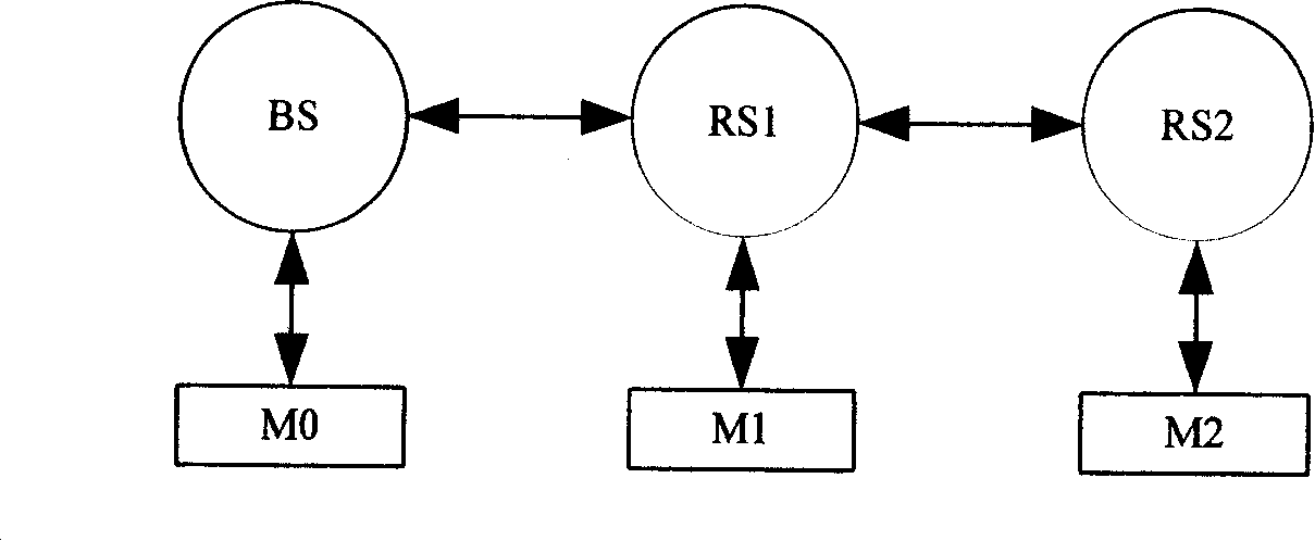
[0055] figure 2 It is a schematic diagram of a multi-hop relay topology structure in an embodiment of the present invention. Such as figure 2 As shown, the multi-hop relay system includes M0, M1, M2, BS, RS1 and RS2. RS1 is cascaded to the lower level of BS, which is the first hop site; RS2 is cascaded to the lower level of RS1, which is the second hop site; M0, M1, and M2 are MSs under the jurisdiction of BS, RS1, and RS2 respectively.

[0056] In the above topology s...


PUM


Abstract

This invention discloses a multi-hop relay method including: data are interacted and transferred between a base station and relays or among relays by relay sub-frames and terminals of the base station, relays or their administrative regions interact service data by terminal sub-frames. This invention also discloses a multi-hop relay system.

Description

technical field [0001] The invention relates to a relay technology in mobile communication, in particular to a multi-hop relay method and a multi-hop relay system. Background technique [0002] In the wireless communication system, due to the attenuation of the path of electromagnetic waves, especially the electromagnetic waves using high-frequency carriers, and the occlusion of buildings, the coverage of the base station (Base Station, BS) is limited, making the wireless communication signal strength in some areas low, the communication quality of a mobile station (Mobile Station, MS) serving as a terminal located in these areas will become very poor. Therefore, in order to solve the problem of small BS coverage caused by electromagnetic wave attenuation, it is usually necessary to use a relay station (Relay Station, RS) to relay the wireless communication signal between the BS and the mobile station to compensate for signal attenuation. [0003] The RS is responsible for ...

Claims


Application Information

Patent Timeline
IPC IPC(8): H04B7/15H04B7/26H04Q7/38H04L27/26
Inventor 尚政张爱民王媛媛李江
Owner 蔡永梅
Why Eureka
Try Eureka