Minitype permanent magnetism synchronization gear wheel free traction machine

A technology of gear traction machine and permanent magnet synchronous motor, which is applied in the field of elevator traction machine and small permanent magnet synchronous gearless traction machine, can solve the problems of increased installation difficulty, complicated processing technology, and increased assembly difficulty, etc. To achieve the effect of easy installation and maintenance, improve safety performance and prolong working life

Inactive Publication Date: 2008-04-30
SUZHOU TORIN DRIVE EQUIP
View PDF3 Cites 12 Cited by
  • Summary
  • Abstract
  • Description
  • Claims
  • Application Information

AI Technical Summary

Problems solved by technology

At present, most of the permanent magnet synchronous gearless traction machines on the market are difficult to meet the above requirements in terms of external dimensions
[0003] China Utility Model Authorization Notice No. CN200943027Y discloses a "small permanent magnet synchronous gearless traction machine". It has the advantages of compact structure, small volume and relatively large load, but the existing problems are: firstly, the support of the traction machine to the traction sheave is a cantilever single-head support structure, so when the traction sheave drives the elevator to work, due to the Unbalanced force, easy to generate vibration, make the work unstable, and the noise is large; secondly, the umbrella-shaped member is used, and the processing technology is complicated; thirdly, in order to prevent the traction rope from jumping out of the traction wheel, the baffle used on the traditional traction machine is adopted. The rope rod not only has many parts and complex structure, but also increases the difficulty of assembly
The disadvantage of this structure is: since the base and the support arm are made separately, in order to ensure the concentricity of the super-long shaft at the fulcrum, the installation heights of the base and the support arm need to be adjusted separately during installation, which not only increases the installation Difficulty, and the installation accuracy cannot be ensured

Method used


Image

  • Minitype permanent magnetism synchronization gear wheel free traction machine
  • Minitype permanent magnetism synchronization gear wheel free traction machine

Examples


Embodiment Construction

[0019] In order to enable the examiners of the patent office and the public to further understand the technical essence and beneficial effects of the present invention, the applicant describes the following with specific but non-exclusive embodiments:

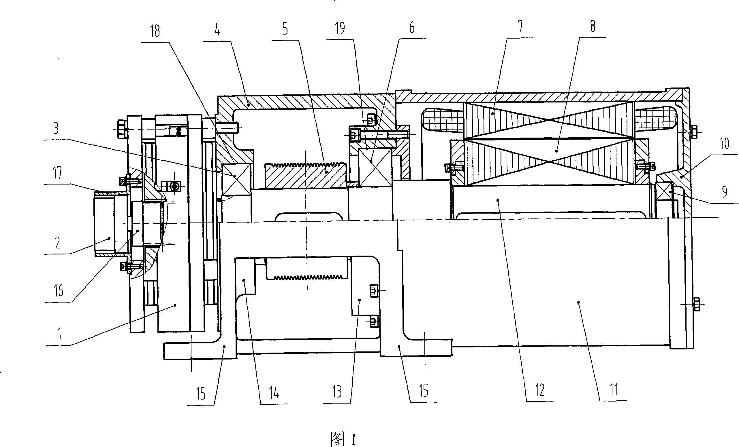
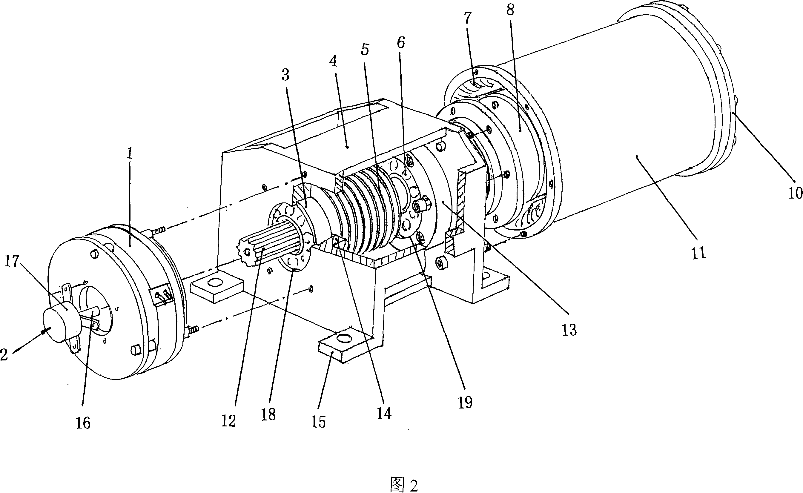
[0020] Please refer to Fig. 1 and in conjunction with Fig. 2, the permanent magnet synchronous motor provided by the present invention is an inner rotor permanent magnet synchronous motor structure, which mainly includes a rotor 8, a stator 7, a sleeve 11, a cylinder cover 10, and the rotor 8 is fixed on the main shaft 12 Above, the stator 7 is sleeved outside the rotor 8, and an air gap is formed between the outer surface of the rotor 8 and the inner surface of the stator 7, and the sleeve 11 is sleeved outside the stator 7. The screw is fixed, the sleeve 11 is fixed on the outside of the right end of the machine base 4 by bolts, and a cover 10 is sealed at the end of the sleeve 11 away from the machine base 4, and a third bear...


PUM


Abstract

A small permanent-magnetic synchronous gearless traction machine belongs to the technical field of lifting facilities, which comprises a base, a brake, a coder, a traction wheel, a main shaft, and a permanent-magnetic synchronous motor. The left and right sides of the base are provided with a couple of first and second bearing bases the centers of which are respectively provided with a first and a second mounting hole. The traction wheel is arranged in the base and sheathed on the main shaft, while the main shaft via first and second bearings is supported on the first and second bearing bases. The permanent-magnetic synchronous motor is an internal-rotor permanent-magnetic synchronous motor, fixed at the outer side of one end of the base. The brake is in disc type, fixed at the outer side of another end of the base. The coder is fixed on the brake and connected with the main shaft via the rotation shaft of the coder. The invention has the advantages that the invention can improve the operation stability, reduce noise and prolong service life of the main shaft, improve the safety of the whole invention, effectively reduce the bearing volume, the invention has small volume, small thickness, high bearing load, easy installment and maintenance, and the invention can eliminate the wire baffle rod used by traditional traction machine.

Description

technical field [0001] The invention relates to an elevator traction machine used in an elevator drive system, in particular to a small permanent magnet synchronous gearless traction machine suitable for elevator traction drive with machine rooms and small machine rooms, and belongs to the technical field of lifting facilities. Background technique [0002] In many cases, existing elevators are installed without a machine room to effectively reduce the floor space, and installing the traction machine on the top of the hoistway is currently the best solution. However, due to the limited space at the top of the original old elevator shaft, the size requirements of the traction machine are relatively strict during the transformation. Space is also required to be as thin as possible in terms of thickness. At present, most permanent magnet synchronous gearless traction machines on the market are difficult to meet the above requirements in terms of external dimensions. [0003] ...

Claims


Application Information

Patent Timeline
Patent Type & Authority Applications(China)
IPC IPC(8): B66B11/04
Inventor 张鹤曹建文房文娜周建
Owner SUZHOU TORIN DRIVE EQUIP
Why Eureka
Try Eureka