Wind turbine impeller installed with blown flap wing-like vane

A technology of airfoil blades and wind turbines, applied in the field of wind turbine impellers, can solve the problems of hindering the flow of airflow on the pressure surface, consuming energy, and difficult to control, etc., and achieve the effects of increasing the utilization coefficient of wind energy, reducing the cost of power generation, and facilitating implementation

Inactive Publication Date: 2008-04-30
申振华
View PDF2 Cites 15 Cited by
  • Summary
  • Abstract
  • Description
  • Claims
  • Application Information

AI Technical Summary

Problems solved by technology

However, for blades with a theoretical thickness of 0 at the trailing edge, this technology is not easy to implement. For example, the structural strength of the Gurney flap when it is connected to the airfoil will bring new problems; and the Gurney flap obviously hinders the pressure The airflow on the surface of the blade flows, so while the lift increases, its resistance may increase even more; another important problem is that it is not easy to control, so there is a jet of air at a certain angle to the blade surface instead of The flap method, that's the jet flap
The effect of the jet flap is related to the position of the jet on the chord line of the airfoil, the direction of the jet and the size of the jet volume; since the jet volume can be controlled, the effect is better than that of the Gurney flap, and the jet volume is determined by The air source that produces the jet is used to control; the usual air source is a fan, of course, this requires additional energy consumption
Gurney flap technology is usually used on aircraft wings, helicopters and rotary impeller machinery, but all these applications (if any) are supplied by a dedicated fan, that is, active jets, which require additional energy consumption. energy

Method used


Image

  • Wind turbine impeller installed with blown flap wing-like vane
  • Wind turbine impeller installed with blown flap wing-like vane
  • Wind turbine impeller installed with blown flap wing-like vane

Examples


Embodiment Construction

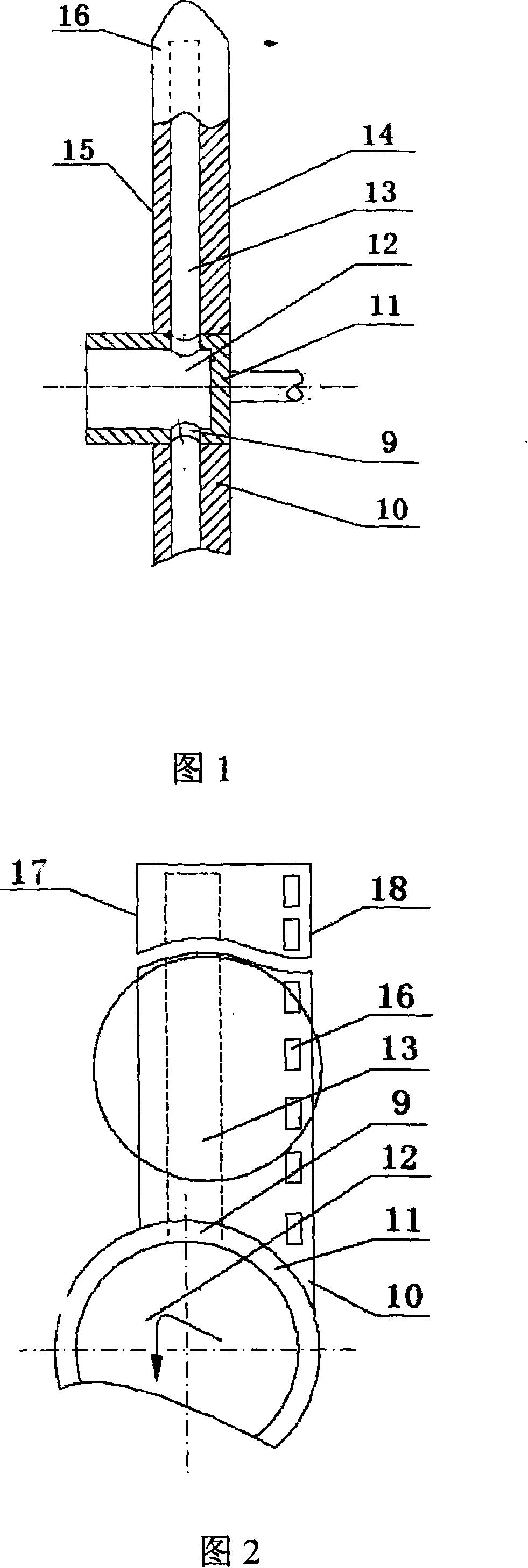
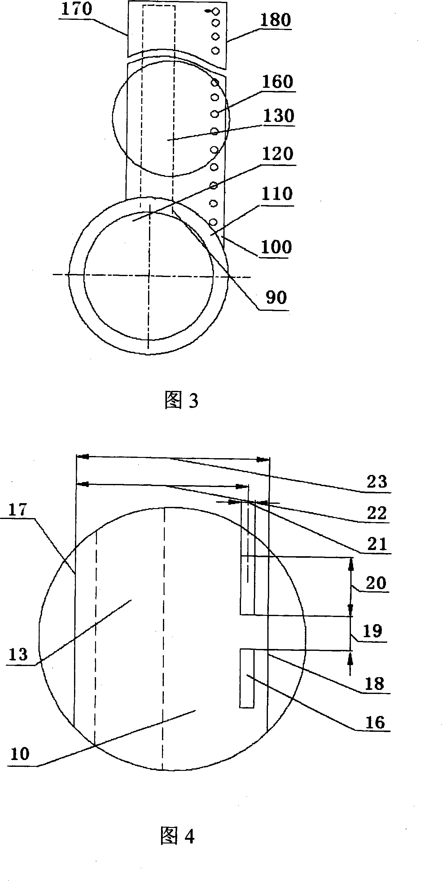
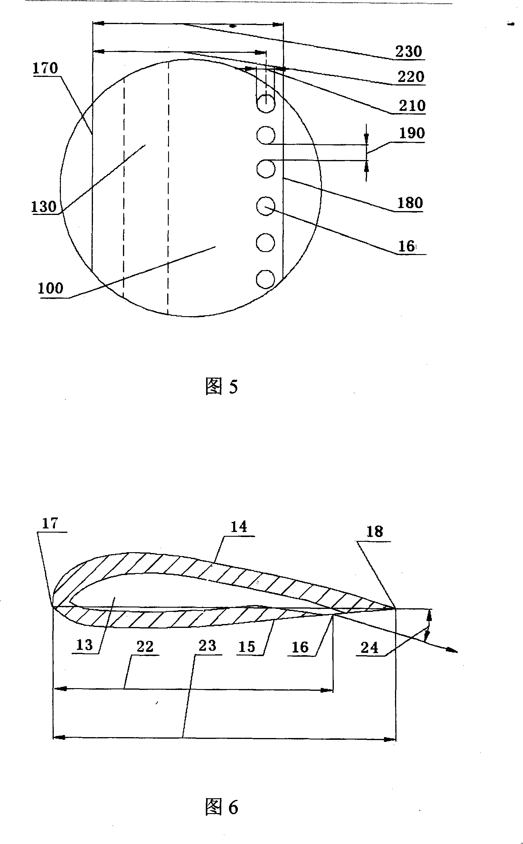
[0018] With reference to Fig. 1 and 9, wind turbine wind wheel among the present invention is made up of blade 10 and hub 11, and wherein blade 10 and hub 11 are all hollow, and blade 10 has suction surface 14 and pressure surface 1, the trailing edge of pressure surface 15 There is a row of fumaroles 16 nearby. When the wind turbine is working, the front wind 1 enters through the hole 12 on the hub, and enters the hole 13 in the blade through the hole 9 on the peripheral wall of the hub, and then sprays out from the jet hole 16 on the pressure surface. The jet holes can only be distributed in the blade tip region, or the middle part of the blade, or the root region on the blade pressure surface 15, or can be distributed in any two regions of the blade tip, middle part or root; they can also be distributed in the whole blade On the pressure surface 15, from the blade root to the blade tip.

[0019] With reference to Fig. 2, this is an embodiment of the present invention, and ...


PUM


Abstract

The invention provides a wind-turbine impeller provided with an air-jetting flap airfoil blade. On the airfoil tail edge of the blade or on the pressure face near the tail edge, for example, apart from the front edge at a distance of 80-100 percent of the airfoil string length, a row of air-jetting holes are drilled from the blade tip to the blade root or in a range with selected radius on the blades. The angle between the air-jetting direction and the airfoil string is controlled between 15 and 90 DEG. Using air-jetting to replace the function of the conventional flap improves the output power of the wind-turbine, lowers the starting wind-speed, enlarges the working range, as well as consumes no additional power, and lowers the electricity generating cost. The air-jetting is produced when the rotating centrifugal force of the blade sucks the air in front of a hollow wheel hub.

Description

technical field [0001] The invention relates to a wind turbine impeller equipped with airfoil blades of jet flaps, specifically a blade of a horizontal axis wind turbine with flaps generated by jet flow, and belongs to the field of design, manufacture and application of wind turbines. Background technique [0002] For decades, people have been pursuing how to improve the efficiency of wind energy utilization of wind turbines. US4197053 proposed a scheme that passively intakes air from the front of the hollow hub and then injects air from the trailing edge of the blades, which reduces the starting wind speed of the wind turbine. , thereby expanding the working range of the wind turbine. [0003] CN03134065.2 greatly broadens the scope of application of the above-mentioned technology. It considers the engineering needs, opens the air jet holes on the blades on the pressure surface, and the air jet direction is the tangential direction of the impeller rotation, which is the so-...

Claims


Application Information

Patent Timeline
Patent Type & Authority Applications(China)
IPC IPC(8): F03D1/06
CPCY02E10/721Y02E10/72
Inventor 申振华
Owner 申振华
Why Eureka
Try Eureka