
A thyristor trigger method

A thyristor and high-voltage thyristor valve technology, applied in electrical components, pulse technology, electronic switches, etc., can solve problems such as difficulty in realization and difficulty in obtaining energy, and achieve the effect of reducing output energy, being easy to realize, and requiring low triggering power.

Inactive Publication Date: 2008-04-30
CHINA ELECTRIC POWER RES INST
View PDF0 Cites 6 Cited by
  • Summary
  • Abstract
  • Description
  • Claims
  • Application Information

AI Technical Summary

Problems solved by technology

However, this DC trigger requires the trigger circuit to output a large amount of energy, which may be possible in some low-power, infrequently triggered applications, but for high-power, frequently triggered applications, especially when the triggered thyristor is at high potential, When it is difficult to obtain energy, it is often difficult to achieve

Method used


Image

  • A thyristor trigger method
  • A thyristor trigger method
  • A thyristor trigger method

Examples


Embodiment Construction

[0010] The present invention will be described in further detail below in conjunction with the accompanying drawings and specific embodiments.

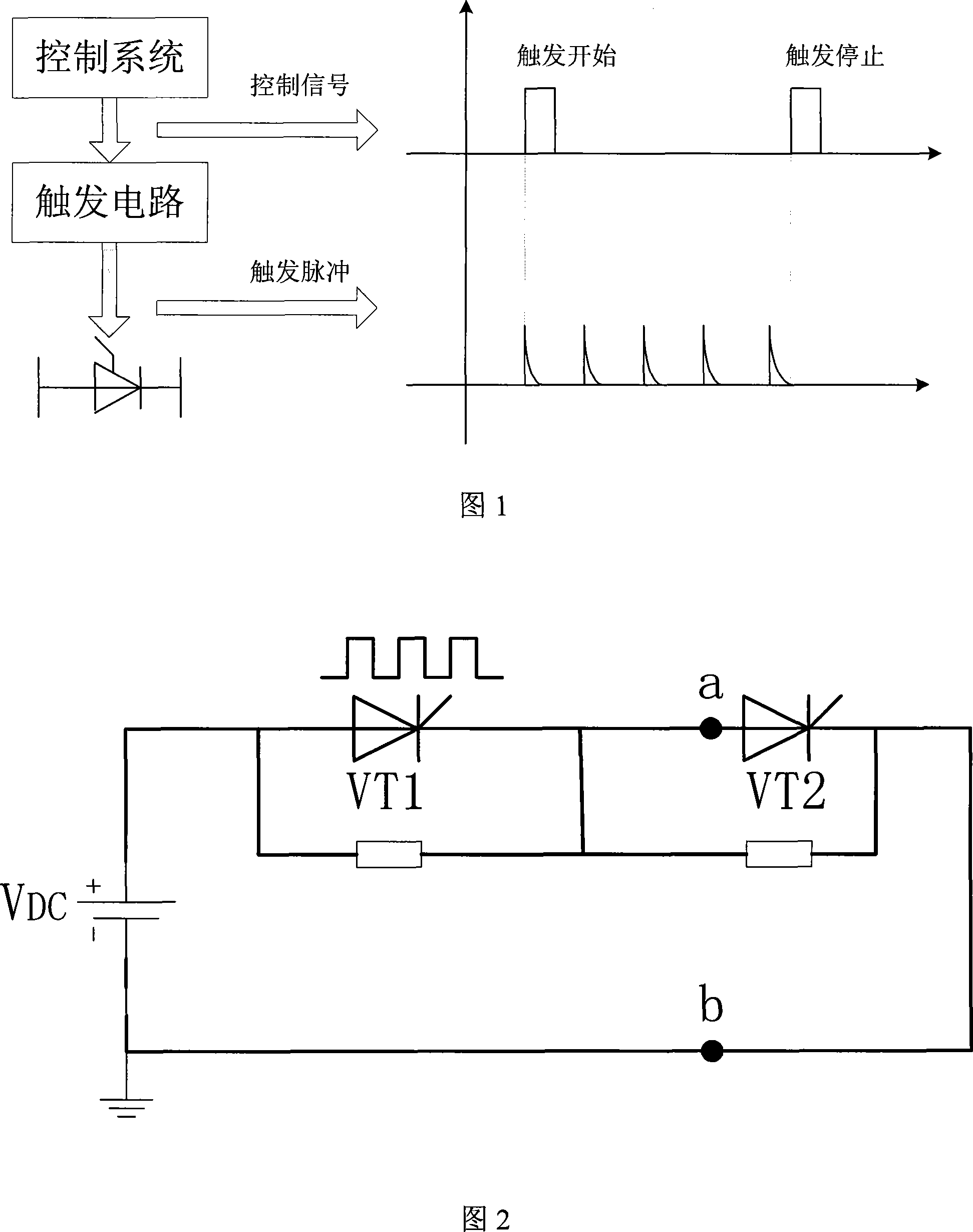
[0011] The schematic diagram of the trigger scheme is shown in Figure 1. When there is no current path or the current path cannot be realized continuously and the thyristor valve needs to be kept in a low-resistance state, the control system sends a trigger start signal, and the trigger circuit immediately sends out a high-frequency signal after receiving the trigger start signal. The pulse train is added to the gate of each thyristor valve to meet the control requirements. Each pulse signal of the high-frequency pulse train meets the basic triggering requirements of the thyristor, and the frequency of the high-frequency pulse train should be greater than 500 Hz.

[0012] Each pulse leading edge satisfies the condition of strong triggering of a general thyristor, which can promote the redistribution of the carrier concentration inside...


PUM


Abstract

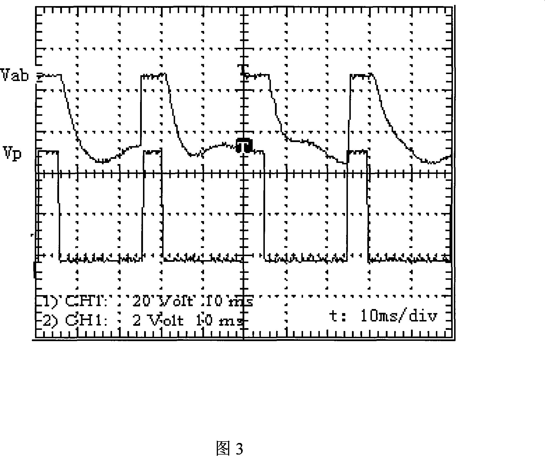
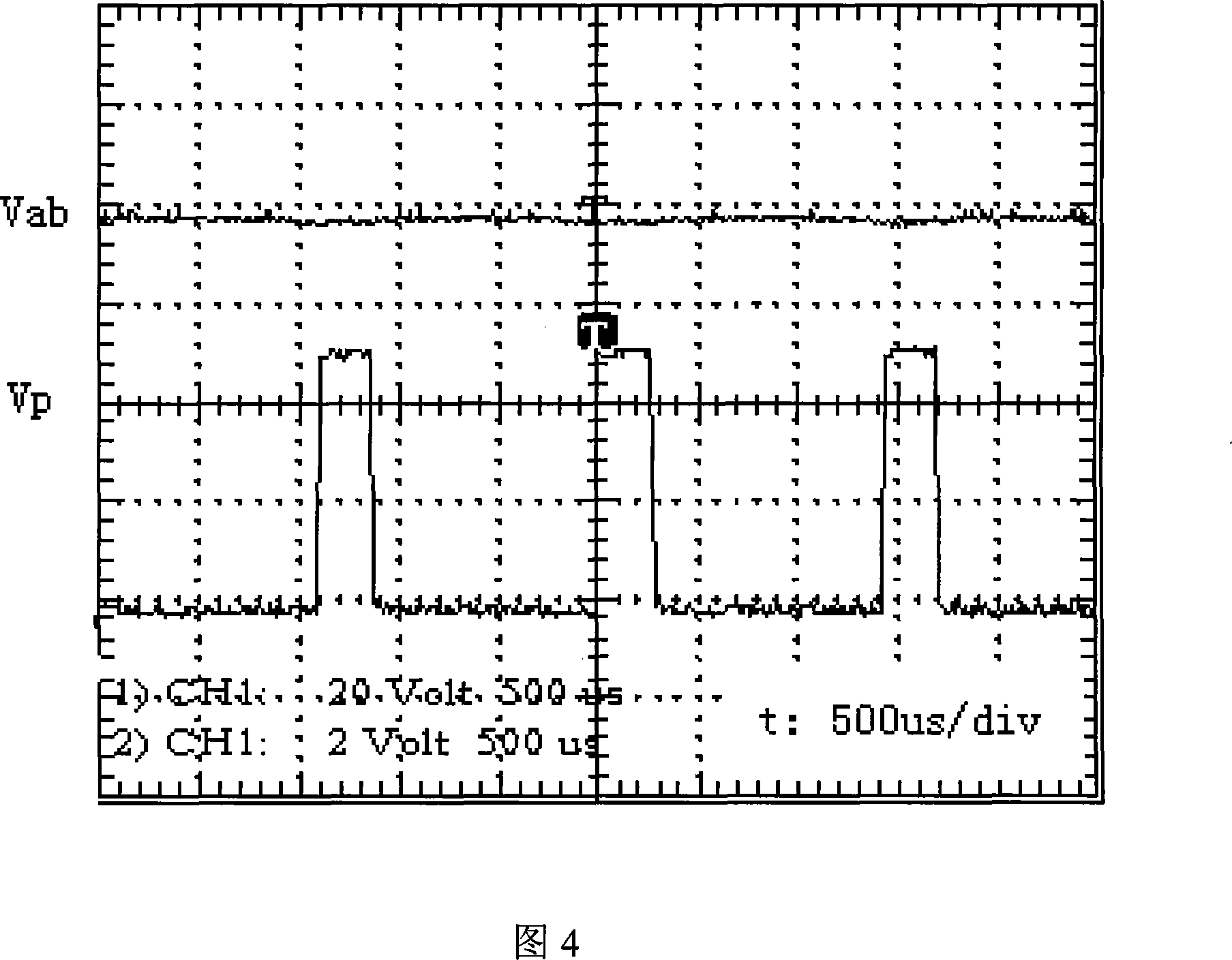
The invention discloses a thyristor trigger method with low trigger power and easy realization. The technical proposal is as follows: high frequency pulse train is persistently imposed on the gates of all serial thyristors in a high-voltage thyristor valve; the frequency of the pulse train should exceed 500Hz, and each pulse edge meets conditions for the strong triggering of ordinary thyristors. When the frequency of the triggering pulse reaches 700Hz, the effect of high-frequency pulse train triggering is equivalent to that of direct triggering. The invention replaces direct triggering with the persistent triggering of thyristors, which triggers thyristors through high-frequency pulse train to greatly lower the output energy of triggering current. Therefore, the power required is low, and the realization is easy.

Description

technical field [0001] The invention belongs to the field of electrical and electronic technology, and relates to a thyristor trigger method. Background technique [0002] Under normal use conditions, the thyristor can maintain the conduction state after the pulse trigger under the forward voltage and a certain maintenance current without continuing to give it a trigger signal, but in some application fields, because there is no current path, the thyristor accepts the trigger If the minimum optima current and maintenance current required by the signal cannot be reached, the low impedance state of the thyristor cannot be achieved; in order to achieve this mode of operation, the thyristor can be triggered by a DC trigger method. The mechanism is: the thyristor adopts a DC Triggering can make the thyristor in a low impedance or continuous conduction state, so as to realize functions such as potential transfer and thyristor protection. However, this DC trigger requires the trig...

Claims


Application Information

Patent Timeline
IPC IPC(8): H03K17/72
Inventor 贺之渊汤广福温家良查鲲鹏魏晓光邓占峰
Owner CHINA ELECTRIC POWER RES INST
Learn More