

Ethernet transmission apparatus and Ethernet signal transmission method
A technology of a transmission device and a transmission method, which is applied in the field of Ethernet communication, can solve problems such as image mosaic, Ethernet data interference, and high ringing signal amplitude, and achieve the effect of reducing impact and strong anti-interference ability
- Summary
- Abstract
- Description
- Claims
- Application Information
AI Technical Summary
Problems solved by technology
Method used
Image

Examples
Embodiment Construction
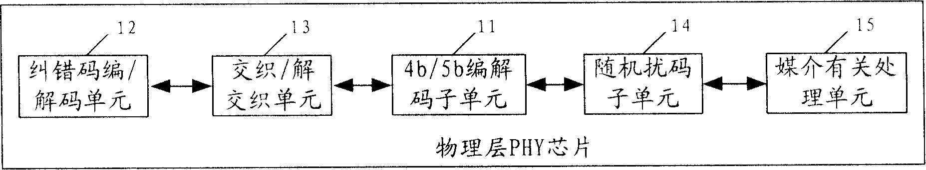
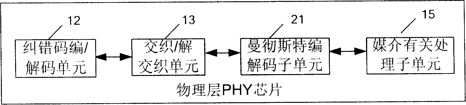
[0028] The technical solution of the present invention will be described in detail below through structural schematic diagrams of several embodiments of physical layer PHY chips disclosed in the present invention. As far as the present invention is concerned, the physical layer PHY chip corresponds to an Ethernet transmission device. Since the main difference of each preferred embodiment lies in the connection relationship between the internal components, for the convenience of description, the connection relationship between the internal components in each embodiment is firstly introduced in conjunction with the accompanying drawings, and then the present invention is introduced in detail. Invented newly added internal logic units: error correction code encoding / decoding unit and interleaving / deinterleaving unit.
[0029] see figure 1 , which is a schematic structural diagram of a first embodiment of a physical layer PHY chip disclosed in the present invention. The PHY chip...
PUM
 Abstract
Description
Claims
Application Information