Electric tool

A technology for electric tools and front ends, which is applied in the direction of motor tools, manufacturing tools, portable motor devices, etc., can solve the problems that the output shaft cannot be shortened, the compactness limit of the front and rear lengths, etc., and achieve good operability and workability, and good operation Sexuality, the effect of a simple swipe operation

Active Publication Date: 2011-02-09
MAKITA CORP
View PDF1 Cites 0 Cited by
  • Summary
  • Abstract
  • Description
  • Claims
  • Application Information

AI Technical Summary

Problems solved by technology

[0005] In such an electric tool, a compact structure is required in consideration of the operability in a narrow place, but if the above-mentioned clamping sleeve is arranged on the output shaft of the anvil or the like, it must be located in front of the housing. The installation space of the clamping sleeve is secured, therefore, the output shaft protruding from the housing cannot be shortened, so there is a limit to the compactness of the front and rear lengths

Method used


Image

  • Electric tool
  • Electric tool
  • Electric tool

Examples


Embodiment Construction

[0016] Embodiments of the present invention will be described below with reference to the drawings.

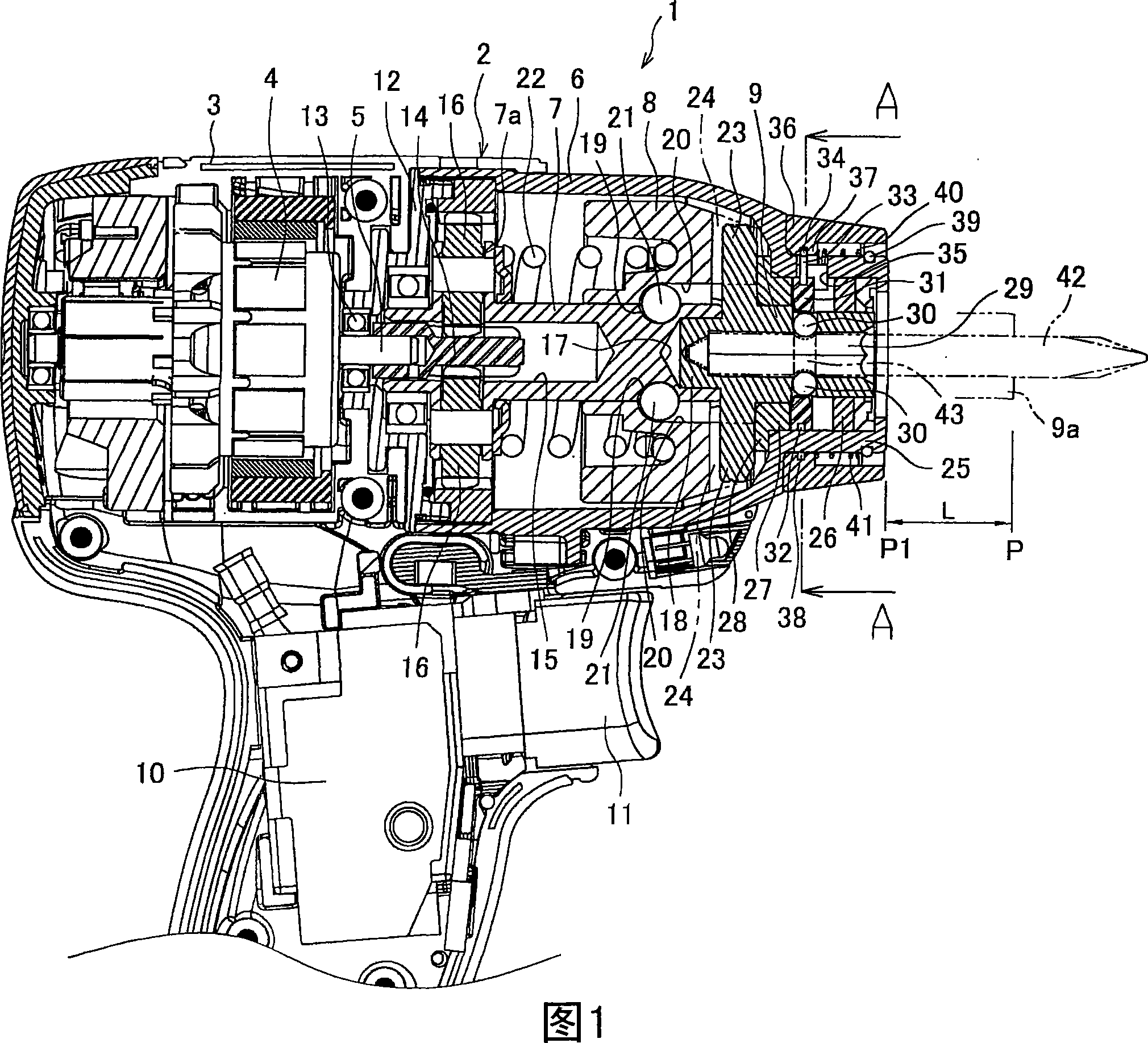
[0017] figure 1 It is a partial longitudinal sectional view of an impact screwdriver as an example of an electric tool. The main body 2 of the impact screwdriver 1 is formed by installing a hammer housing 6 in front of a main body housing 3 housing a motor 4. The hammer housing 6 accommodates a main shaft 7, a hammer 8, an anvil 9 serving as an output shaft, and the like. 10 is a switch for driving the motor 4, and 11 is a trigger for turning the switch on / off.

[0018] The gear box 12 is interposed between the main body housing 3 and the hammer housing 6, and the gear box 12 supports the motor shaft 5 of the motor 4 through a ball bearing 13, and makes the pinion gear 14 embedded on the motor shaft 5 The inside of the hammer housing 6 protrudes. The motor shaft 5 and the pinion 14 are loosely inserted into the hollow portion 15 formed at the rear end of the main shaft 7 i...


PUM


Abstract

The invention provides an electric tool, realizing the compaction of the front and back lengths. The invention is characterized in that: a tubular part (25) of an anvil stand (9) with axle suspension is arranged at the front end of a hammer shell (6); a steel ball (30) in an insertion hole (29) of the tool head is positioned between bearing collars (26, 27) of the anvil stand (9) in the tubular part (25); an exterior locking ring (31) moves back and forth between a locking position pressing the steel ball (30) to a convex position and a unlocking position for the pressed steel ball (30); an operating sleeve (36) is externally arranged under the condition that the tubular part (25) is capable of moving back and forth and loading towards the back moving, and connected with the locking ring (31) after passing through a wire frame (33) and over the tubular part (25), enabling the locking ring (31) to move between the locking and the unlocking positions.

Description

technical field [0001] The present invention relates to an electric power tool having an output shaft for detachably inserting a tool head into a front end portion of a main body in which a motor is built. Background technique [0002] In the electric tool, as the impact screwdriver shown in Patent Document 1 is known, the main shaft rotated by the drive of the motor is pivotally supported in the casing, and the output shaft protruding forward is pivotally supported at the front end of the casing. The anvil is provided on the anvil with a hammer that engages with the anvil to transmit the rotation of the main shaft to the anvil. According to the load acting on the anvil, the hammer engages and disengages from the anvil to apply force to the anvil. Strike action in the direction of rotation. [0003] On the other hand, on the anvil, an insertion hole for a screwdriver bit (that is, a tool bit) is formed at the center of the shaft, and a steel ball that can go in and out of t...

Claims


Application Information

Patent Timeline
Patent Type & Authority Patents(China)
IPC IPC(8): B25B21/02B25F5/00B23B31/107
Inventor 长坂英纪
Owner MAKITA CORP
Why Eureka
Try Eureka