

Plane multiple joint robot
A plane multi-joint, robot technology, used in manipulators, claw arms, manufacturing tools, etc., can solve the problems that the manipulator cannot be used in a high-clean environment, and the manipulator does not have a sealing device, and achieves a simple and reliable structure. The effect of machine strength
- Summary
- Abstract
- Description
- Claims
- Application Information
AI Technical Summary
Problems solved by technology
Method used
Image

Examples
Embodiment 1
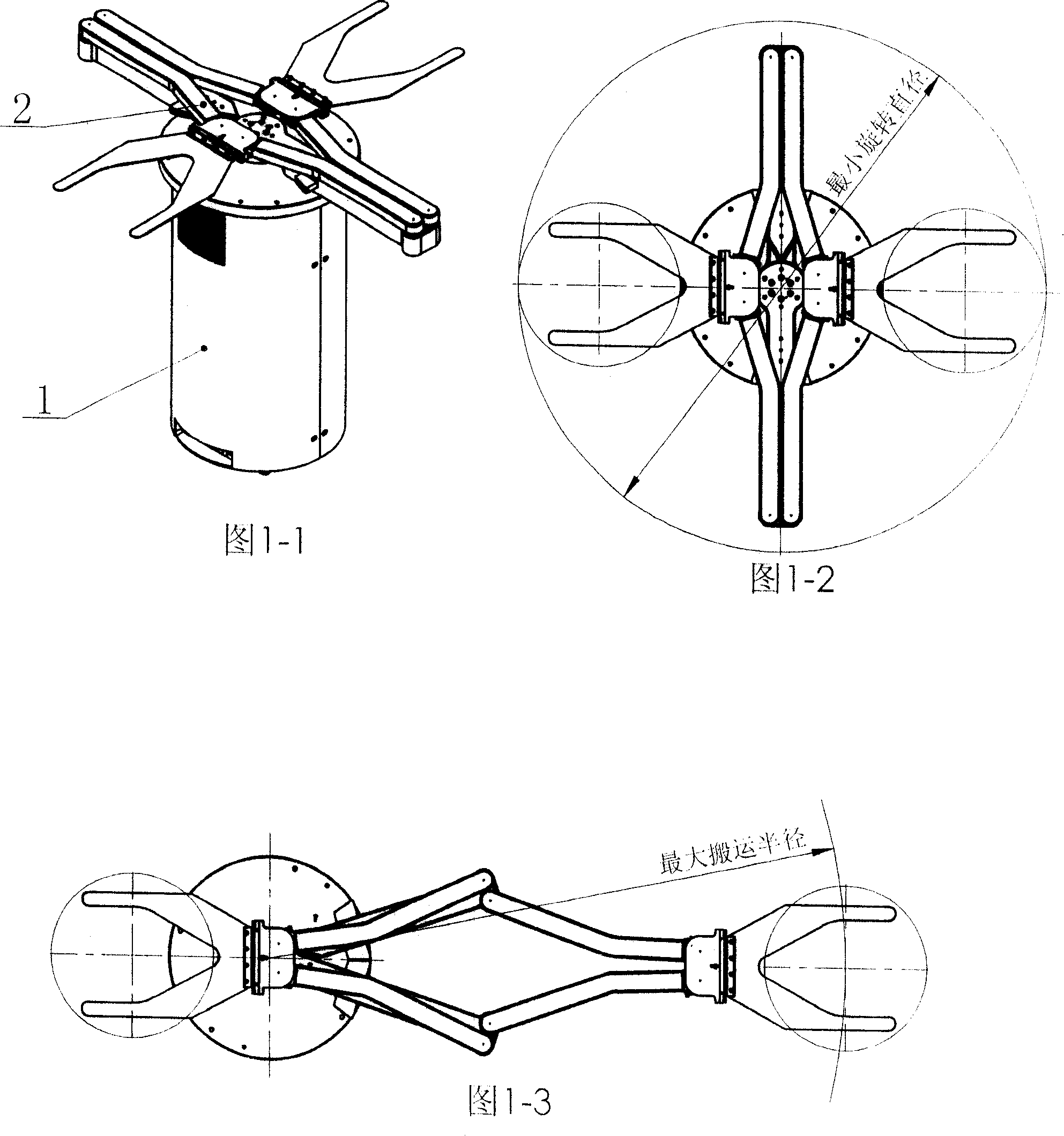
[0047] As shown in Figure 1-1, the planar multi-joint robot of the present invention is a handling robot with a symmetrical double-arm structure, which consists of a column assembly 1 and a symmetrical double-arm assembly 2 to realize the lifting, rotating and telescopic movements of the end effector.
[0048] As shown in Figure 1-2, the arms are retracted to the middle position.
[0049] As shown in Figure 1-3, it is the maximum stretch position of the right arm.
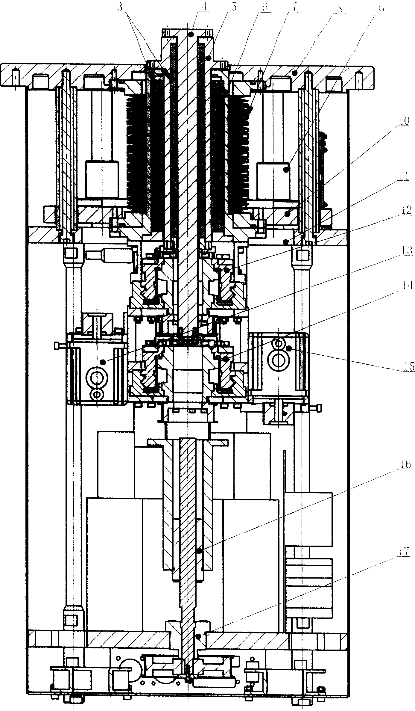
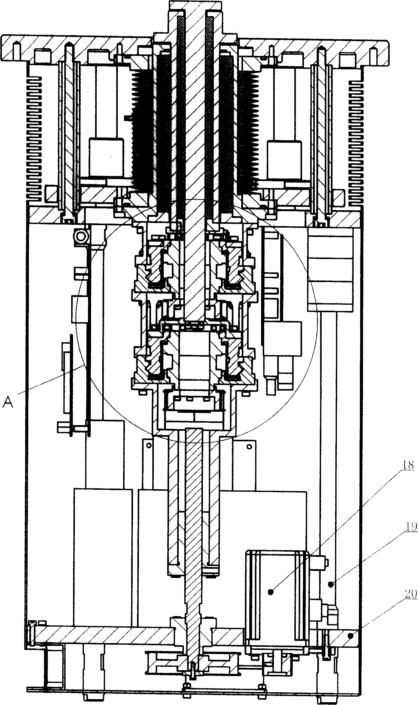
[0050] Such as diagram 2-1 , 2-2 , 2-3, and 2-4, the structure of the column assembly 1 is composed of a lifting drive device, an inner shaft, an outer shaft rotation drive device, a linear guide, a linear seal and a rotary seal device, and an outer cover; wherein:
[0051] Lifting driving device comprises leading screw screw nut 16, leading screw support 17, lifting motor 18, lower fixed plate 20, screw nut connecting seat 23, and the lifting motor 18 that is fixed on the lower fixed plate 20 passes synchronous ...
Embodiment 2
[0067] The telescopic arm assembly 2 given in Embodiment 1 belongs to the symmetrical double-arm structure with the same height as the end effector, and the arm structure of the telescopic arm assembly 2 given in this embodiment is a single-arm structure.
[0068] As shown in Figure 3-1, it specifically includes: the first big arm 24, the second big arm 33, the second small arm 26, the third small arm 31, the first connecting seat 27, the first end effector 28, the first One big arm 24 is installed on the upper end of the outer shaft 5 in the linear guide, linear seal and rotary seal device, the second big arm 33 is installed on the upper end of the inner shaft 4 in the linear guide, linear seal and rotary seal device, the first big arm The end of the second arm 24 is hinged with the head of the second arm 26, the end of the second arm 33 is hinged with the head of the third arm 31, and the ends of the second arm 26 and the third arm 31 are hinged with the first connecting seat...
Embodiment 3
[0071] The arm structure of the telescopic arm assembly 2 given in this embodiment is a double-arm structure in which the end effectors are not equal in height.
[0072] Such as Figure 5 As shown, specifically: it is composed of two sets of single-arm structural components given in Example 2, and the two sets of single-arm structural components are arranged in an upper-lower stacked arrangement to form an upper-lower overlapping double-arm structure with unequal heights of end effectors.
[0073] Its working process is identical with embodiment 1.
PUM
 Abstract
Description
Claims
Application Information