Displace type LED energy conserving lamp, lamps and driver thereof

A LED energy-saving lamp, a replacement technology, applied in the direction of electric lamp circuit layout, semiconductor devices of light-emitting elements, and damage prevention measures for lighting devices, etc., can solve the problems of inconsistent LED brightness, LED group damage life, and current increase. Achieve the effect of solving the uniformity of brightness and LED life, solving the problem of heat dissipation, and avoiding the increase of current

Active Publication Date: 2011-06-22
DONGGUAN PERFECT SCI & TECH
View PDF0 Cites 0 Cited by
  • Summary
  • Abstract
  • Description
  • Claims
  • Application Information

AI Technical Summary

Problems solved by technology

At present, many high-power LED driving circuits on the market adopt constant voltage driving mode. The disadvantage of this mode is that as the current of the circuit changes, the brightness of the LED will be bright and inconsistent. At the same time, due to the damage of an LED in the LED group, the overall The current becomes larger, it is easy to cause damage to the entire LED group and shorten the life, so this kind of driving circuit needs to be improved urgently.

Method used


Image

  • Displace type LED energy conserving lamp, lamps and driver thereof
  • Displace type LED energy conserving lamp, lamps and driver thereof
  • Displace type LED energy conserving lamp, lamps and driver thereof

Examples


Embodiment 1

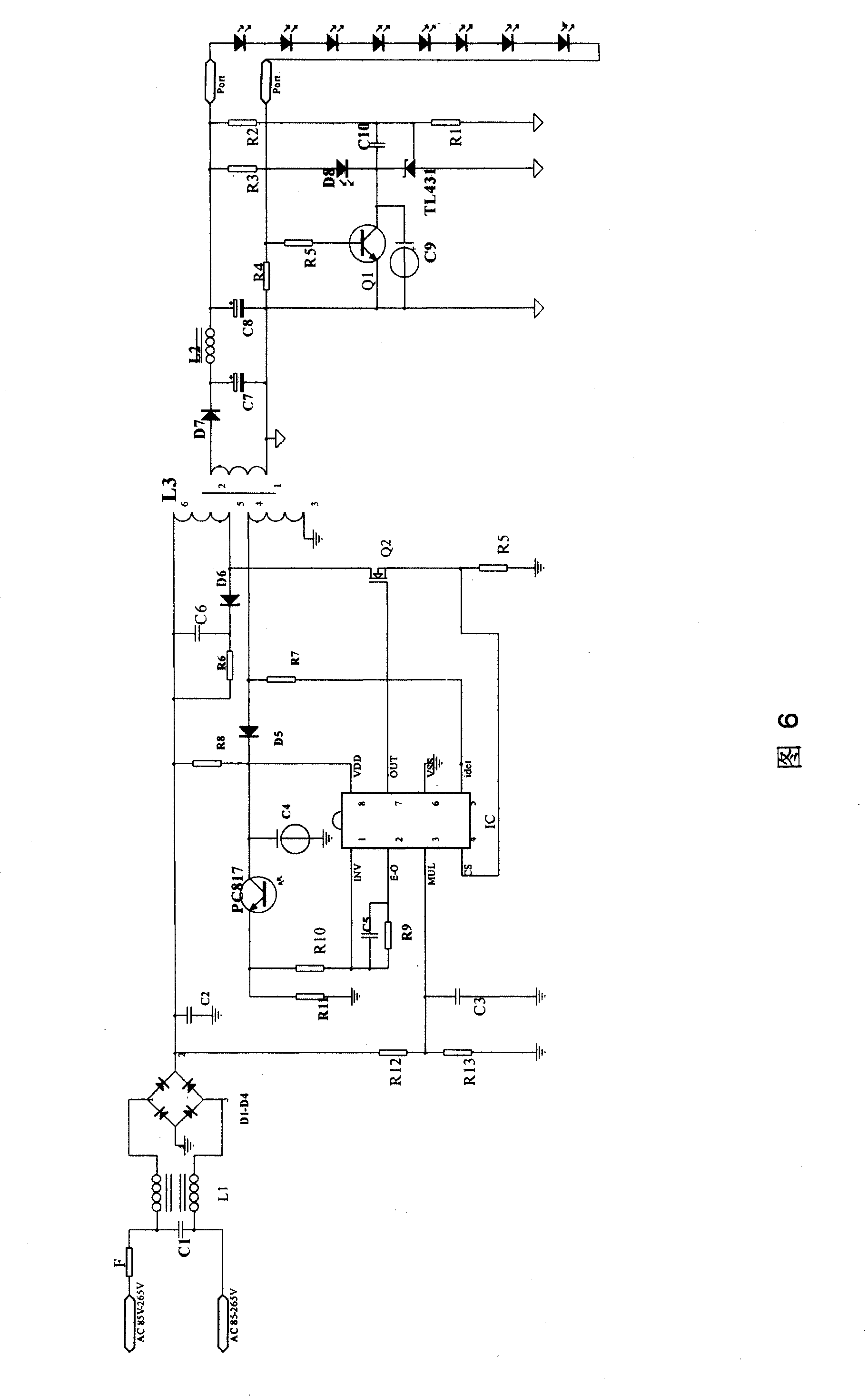
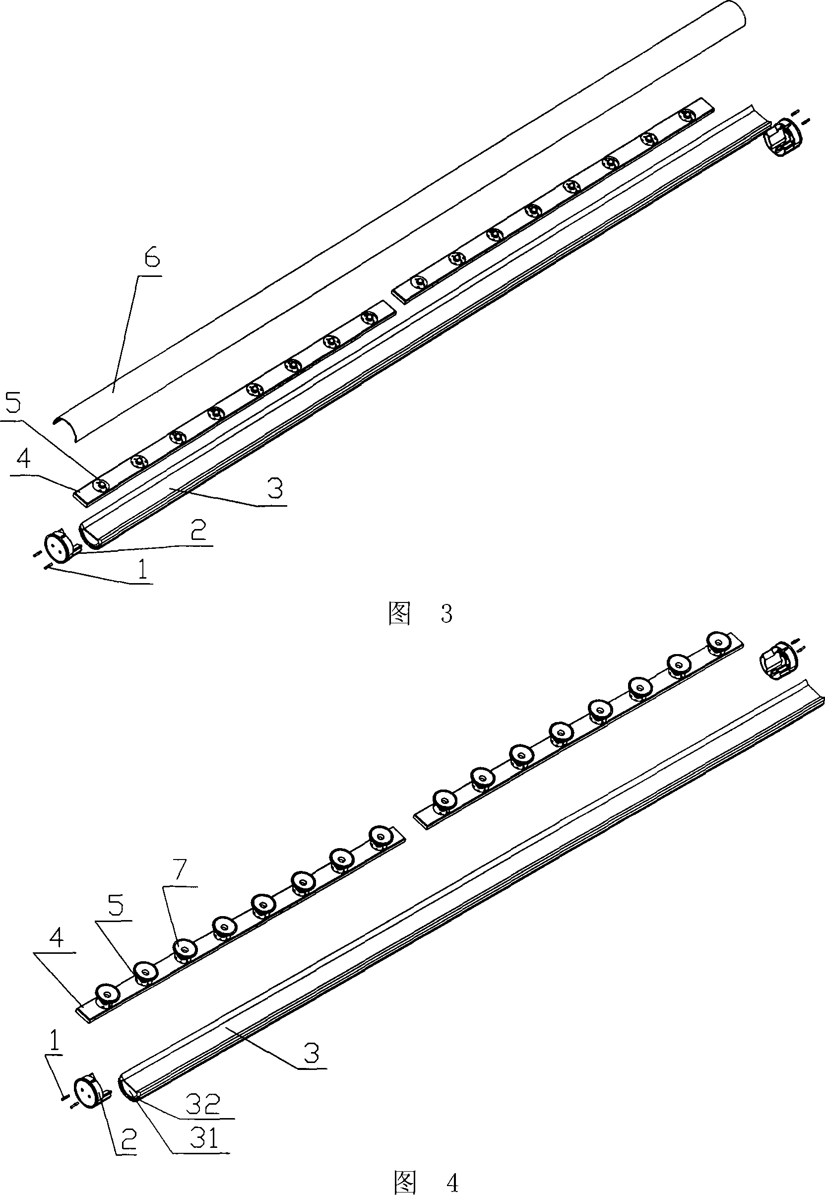
[0031] Embodiment 1: see Figure 1 ~ Figure 4 , a replacement LED energy-saving lamp provided by the present invention, which includes a general-purpose lamp holder 1 and a lamp 12, the lamp 12 is a special replacement LED lamp, and the replacement lamp 12 includes a metal elongated support tube 3 and The plug joints 2, the strip-shaped metal strip plate 4 and a number of LED light sources 5 arranged on the strip plate 4 are arranged at both ends; the strip plate 4 is arranged at the lower part of the elongated support tube 3 and under The end faces are in contact, and the electrodes 1 of the plug connector 2 are electrically connected to the LED light source 5 through wires. In this embodiment, the elongated support tube 3 and the light strip plate 4 are components made of aluminum alloy.

[0032] The elongated support tube 3 is a tubular member with a semicircular cross section and a cavity 31 in the middle, and its lower end surface is Shape, the arc-shaped end face of it...

Embodiment 2

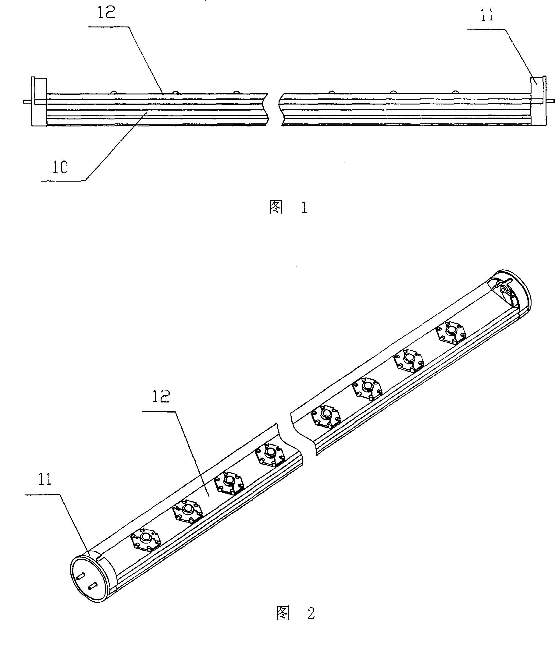
[0040] Example 2: see Figure 4 , its basic structure is the same as that of Embodiment 1, the difference is that the replacement LED lamp 12 is directly manufactured as a T8-type specification, and the described general-purpose lamp holder 10 is also a T8-type, which can be It is directly plugged into the T8-type universal lamp holder 10, so there is no need to set up a special connecting bracket 11; the light strip plate 4 is provided with a number of LED cup-shaped lamp holders 7, and the lamp holders 7 are welded on the light strip plate 4 on the lower end face, and the LED light source 5 is detachably arranged on the lamp holder 7; meanwhile, the rhombic cover 6 is not provided.


PUM


Abstract

The invention discloses a substitutive type LED energy-saving lamp, comprising a long metal frame tube, connection plugs arranged at both ends of the frame tube, a strip metal light band board and a plurality of LED light sources arranged on the light band board, wherein, the light band board is arranged at the lower part of the long metal frame tube and contacted with the lower end surface of the frame tube. The electrodes of the connection plugs are electrically connected with the LED light sources by wires. The invention also discloses a lamp which adopts the substitutive type LED energy-saving lamp and comprises a universal lamp race, the lamp and also a special connecting frame which is a long-shaped assembly comprising a frame body and a demountable connecting plug which is respectively arranged at both ends of the frame body. The external side of the connection plug is provided with two inserting pins inserted on a universal lamp rack socket. Moreover, the invention also discloses an LED driver for the lamp. The invention has reasonable structure and good heat radiation property and the original universal lamp rack can be continuously used when in use.

Description

technical field [0001] The invention relates to an LED lamp, in particular to a replacement LED energy-saving lamp, a lamp and a driver thereof which use LED as a light source and can directly replace existing fluorescent lamps. Background technique [0002] Fluorescent lamps in the prior art belong to gas discharge lamps, also known as hot-cathode low-pressure mercury fluorescent lamps, which replace incandescent lamps and become the second-generation mainstream lighting source. The power of existing fluorescent lamps is mostly between 8 watts and 40 watts. For fluorescent lamps used in workshops and classrooms, each fluorescent lamp often needs to use two lamps in parallel to meet the requirements of light brightness. The power of such a fluorescent lamp It needs 80 watts, and a classroom needs at least six fluorescent lamps, which shows that the power consumption is very large. At present, with the development of solid-state lighting, LED lighting, which combines multipl...

Claims


Application Information

Patent Timeline
Patent Type & Authority Patents(China)
IPC IPC(8): F21V15/02F21V21/108F21V23/06F21V29/02F21V17/00H05B37/02F21Y101/02F21K9/27F21V29/67F21Y103/10F21Y115/10
CPCF21Y2103/003F21Y2101/02F21K9/00F21K9/17F21K9/27F21Y2103/10F21Y2115/10
Inventor 刘世江
Owner DONGGUAN PERFECT SCI & TECH
Why Eureka
Try Eureka