
Shell pipe heat exchanger

A shell-and-tube heat exchanger, shell-and-tube technology, applied in the direction of heat exchanger types, indirect heat exchangers, lighting and heating equipment, etc., can solve the problems of low heat transfer coefficient, heat exchanger failure, cracks in welds, etc. To achieve the effect of increasing the heat exchange area, prolonging the service life and high heat exchange efficiency

Inactive Publication Date: 2008-05-14
SUZHOU QUTU THERMAL CONTROL SYST
View PDF0 Cites 7 Cited by
  • Summary
  • Abstract
  • Description
  • Claims
  • Application Information

AI Technical Summary

Problems solved by technology

There are many welding points in the manufacturing process of this shell-and-tube heat exchanger, and the manufacturing process is complicated, so there is a risk of leakage, and the materials at the welding points are generally not the same material. Due to the different thermal expansion coefficients of various materials, the heat exchanger If working under large temperature fluctuations, thermal stress will appear, and in severe cases, cracks will appear at the weld, which will cause the heat exchanger to fail
Moreover, such a shell-and-tube heat exchanger uses a tube bundle with a large cross-section on the tube side, and the fluid contact surface inside and outside the tube is small, so the conduction heat transfer efficiency that accounts for the main heat transfer mode is low, so the heat transfer coefficient is low, and the volume and weight also larger

Method used


Image

  • Shell pipe heat exchanger
  • Shell pipe heat exchanger

Examples


Embodiment

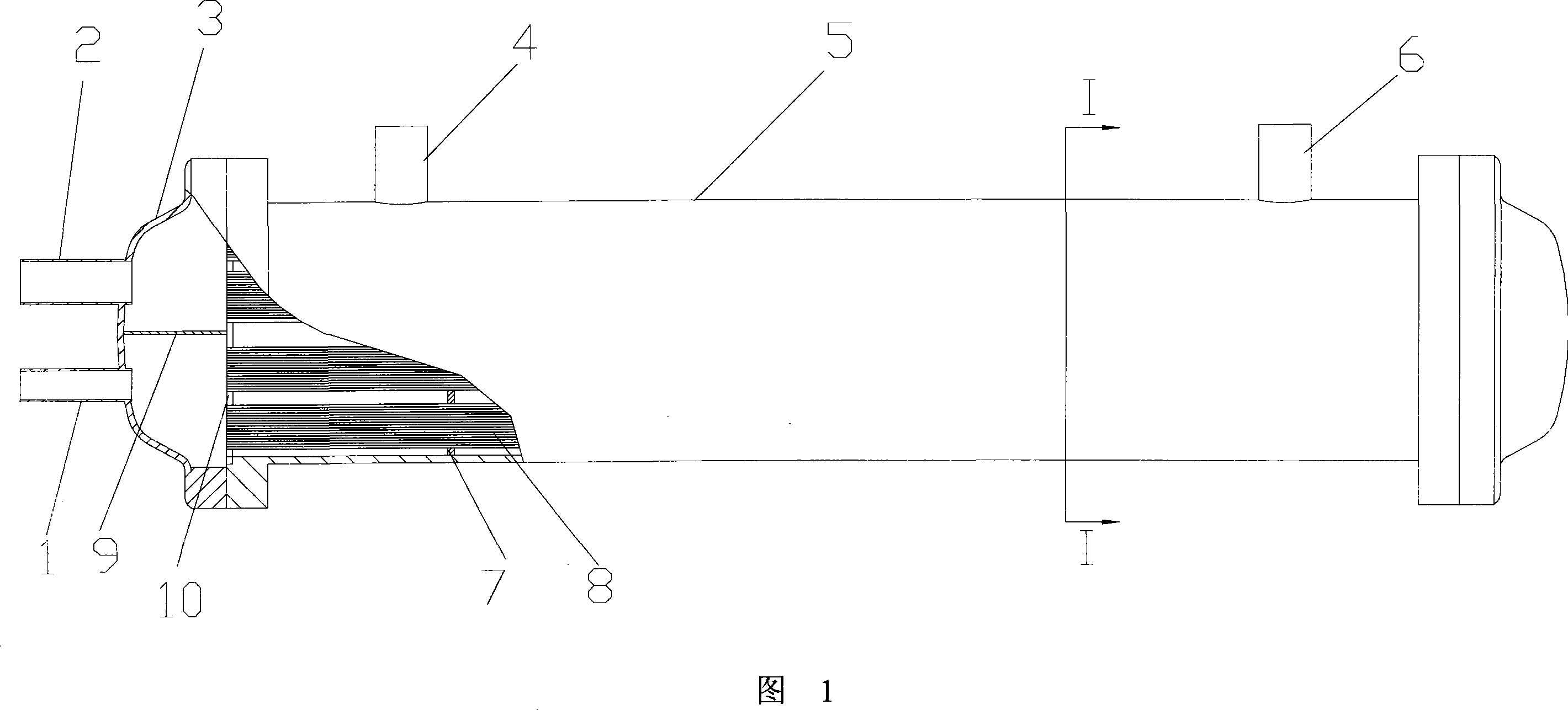
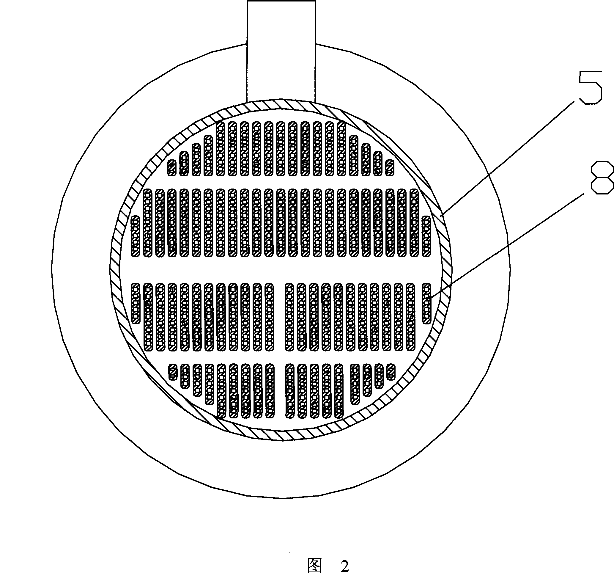
[0014] Embodiment: As shown in Figure 1 and Figure 2, a shell and tube heat exchanger includes a shell tube 5 and end caps 3 at both ends of the shell tube 5 in the axial direction. A plurality of parallel tube bundles 8 and tube sheets 10 connected to both ends of the tube bundles 8, the end cover 3 is provided with a tube-side inlet 2 and a tube-side outlet 1, and the tube shell 5 is provided with a shell-side inlet 4 and shell side exit 6.

[0015] There is also a baffle 9 between the end cover 3 and the tube sheet 10 on the same side, which divides the space between the end cover 3 and the tube sheet 10 into several separate cavities, so that the circulation of the fluid in the heat exchange flat tube is divided into Several tube passes are added, which is more conducive to heat exchange.

[0016] In order to increase the flow velocity of the fluid in the shell side and enhance the disturbance, several baffles 7 are arranged on the entire length of the shell tube to defle...


PUM


Abstract

The invention discloses a shell tube heat exchanger, comprising a shell tube and axial end covers at two ends of the shell tube. A plurality of bundles which are axially parallel with the shell tube and tube plates connected with two ends of the bundles are arranged in an internal part of the shell tube. A tube-side inlet and a tube side outlet are arranged at the end covers. A shell side inlet and a shell side outlet are arranged on the shell. Each component of the shell tube heat exchanger is made of the same material. A welding process of the shell tube heat exchanger is that firstly points of each component to be welded are covered by solders; secondly positions are fixed well for a whole vacuum brazing. The invention is formed by components which are made of the same material and are brazed into a whole, with an excellent airproof capability and a light weight. And a heat expansion coefficient of each part is the same, then the invention can be against a low temperature and the capability of the shell tube heat exchanger is enhanced and the service life of the shell tube heat exchanger is prolonged.

Description

technical field [0001] The invention relates to a shell and tube heat exchanger used in refrigeration equipment. Background technique [0002] The shell-and-tube (or shell-and-tube, or tube-and-tube) heat exchanger is composed of a cylindrical shell, a tube sheet, a tube bundle and an end cover. It exchanges heat with two fluids of different temperatures inside and outside the tube bundle. Many small-diameter tubes are placed in the shell of this traditional shell-and-tube heat exchanger, and tube sheets are welded at both ends of the shell and tube, and the small-diameter tubes are welded to the tube sheet, so that the heat exchanger is divided into a shell side and a tube side. Some multi-pass shell-and-tube heat exchangers are also equipped with split-pass partitions, which are welded in the heat exchanger. There are many welding points in the manufacturing process of this shell-and-tube heat exchanger, and the manufacturing process is complicated, so there is a risk of...

Claims


Application Information

Patent Timeline
Patent Type & Authority Applications(China)
IPC IPC(8): F28D7/10
Inventor 刘明国
Owner SUZHOU QUTU THERMAL CONTROL SYST
Learn More