Universal bilateral composite mold integrated circuit pin forming mechanism of nesting structure

A nested structure, integrated circuit technology, applied in the direction of electrical components, electrical components, etc., can solve the large operating error and cumulative error, it is difficult to achieve the precision of molding processing, the consistency of molding pins, and the absolute adjustment cannot meet the requirements of the molding mechanism and Problems such as the connection conditions of the automatic control system, to ensure the forming accuracy and consistency, realize the effect of automatic forming equipment, high-precision automatic forming equipment

Inactive Publication Date: 2008-05-14
BEIJING AEROSPACE GUANGHUA ELECTRONIC TECH CO LTD
View PDF0 Cites 8 Cited by
  • Summary
  • Abstract
  • Description
  • Claims
  • Application Information

AI Technical Summary

Problems solved by technology

However, most of the traditional general-purpose double-sided composite mold forming mechanisms are composed of simple bending and cutting mechanisms. There is no relationship between the bending and cutting mechanisms. The forming height and length of the integrated circuit pins are completed by adjusting the absolute position of the forming parts. , such a molding mechanism will produce large operating errors and cumulative errors, it is difficult to achieve the accuracy of molding processing and the consistency of molding pins, even under the same batch production conditions, it is impossible to have differences in the molding height and length of molding pins Avoided
Moreover, the absolute adjustment of the traditional general-purpose double-sided composite mold forming mechanism cannot meet the conditions for connecting the forming mechanism with the automatic control system

Method used


Image

  • Universal bilateral composite mold integrated circuit pin forming mechanism of nesting structure
  • Universal bilateral composite mold integrated circuit pin forming mechanism of nesting structure
  • Universal bilateral composite mold integrated circuit pin forming mechanism of nesting structure

Examples


specific Embodiment approach

[0023] The specific embodiment of the present invention is set forth below in conjunction with accompanying drawing as follows:

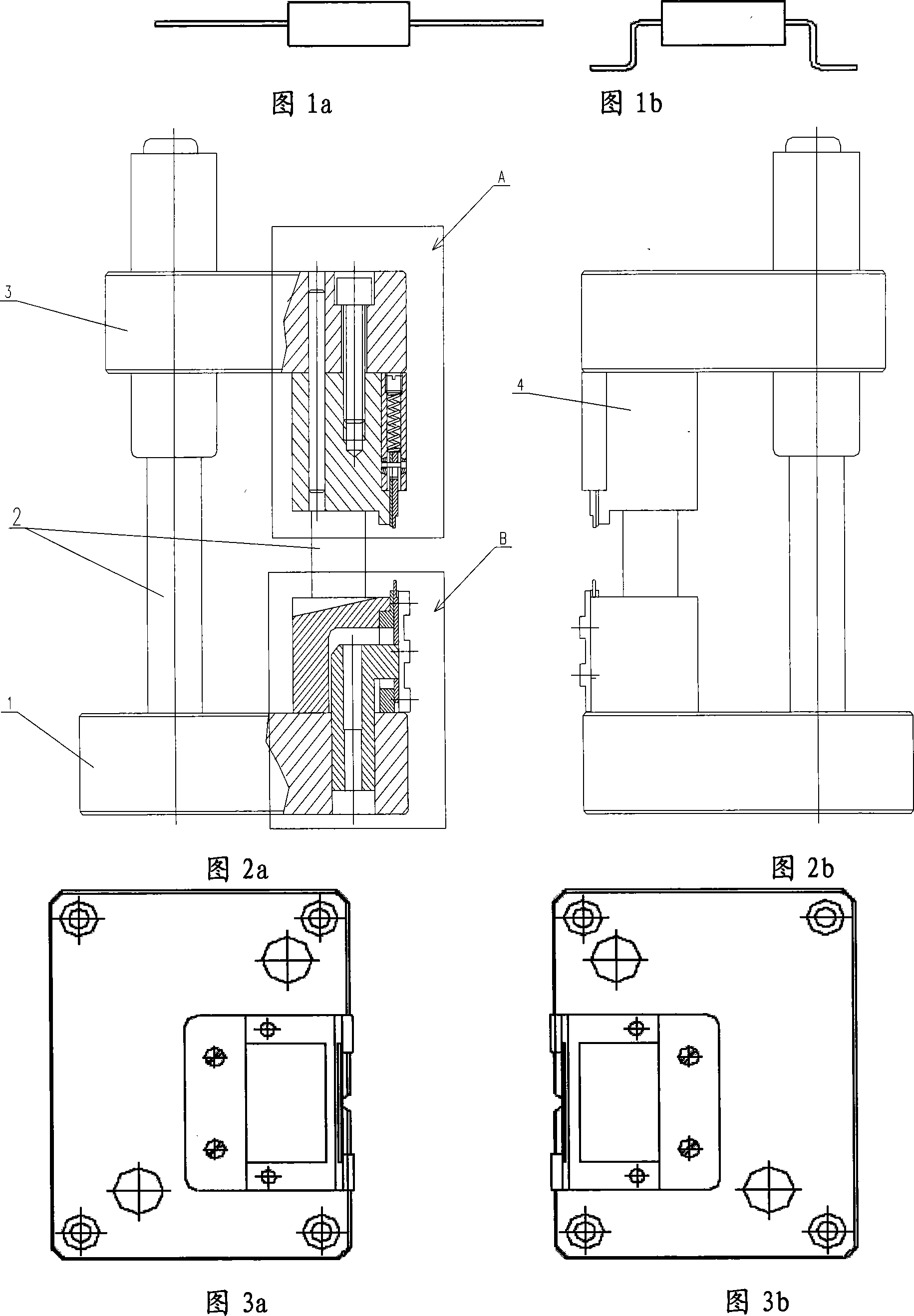
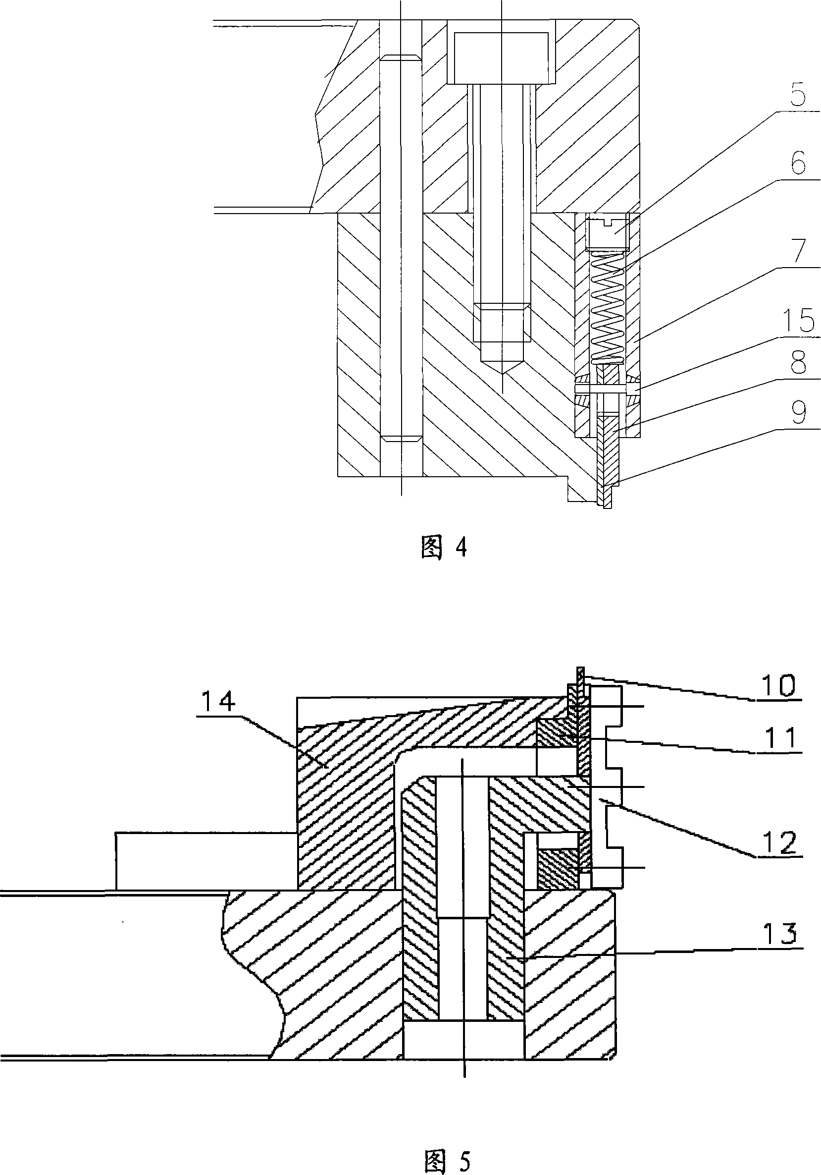
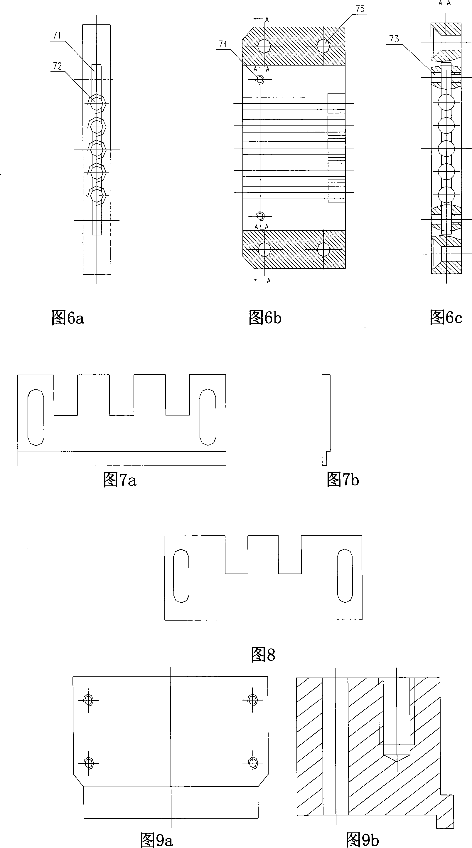
[0024] As shown in Figures 1 to 5, the main structure of the forming mechanism of the present invention is left-right symmetrical, including a left half mold and a right half mold, and each half mold forming mechanism includes a composite mold base 1, a guide post 2, an upper support 3, The upper mold and the lower mold, the lower mold and the guide post 2 are fixed on the composite mold base 1, and the upper mold is fixed on the upper bracket 3, and the upper mold is mainly fixed by the shearing mold 4, the screw 5, the spring 6, and the upper mold plate 7, pressing plate 8 and upper molding die 9, the upper molding die 9 and pressing plate 8 are fitted together and nested in the upper die fixing plate 7, and the screw 5 and the spring 6 installed in the upper die fixing plate 7 will The upper forming die 9 and the pressing plate 8 are ejected outw...


PUM


Abstract

The invention provides a molding mechanism for pins on integrated circuit of general bilateral compound die with a nest structure that has a left and right symmetric structures formed by two semi-die molding mechanisms; wherein, each semi-die molding mechanism contains a compound die base, a guide pillar, an upper die and a lower die; the lower die and the guide pillar are fixed on the compound die base; the upper die is fixed on an upper support and consists essentially of a shearing die, a bolt, a spring, an upper die fixing plate, a pressing plate and an upper forming die, while the lower die essentially consists of a support plate, a lower forming die, a support plate pressing plate, a support guide block and a lower die pressing plate. The invention realizes the regulation of molding height and length of the integrated circuit pins by regulating the relative positions of molding parts and finishes pin molding and shearing work procedure in one time, which ensures the molding precision and consistency of the integrated circuit to pin and meet connection requirement of the molding mechanism and automatic control system.

Description

technical field [0001] The invention relates to a forming mechanism for integrated circuit pins, in particular to a forming mechanism for universal bilateral composite mold integrated circuit pins with a nested structure. Background technique [0002] With the continuous advancement of science and technology, surface mount technology (SMT) is more and more widely used in aerospace research and production and other fields. The integrated circuit pin forming mechanism is a new type of mechanism developed based on SMT. It is used to process the straight pins of the integrated circuit into a pin shape that can be used for surface mounting. The integrated circuit before and after forming is shown in Figure 1. The molding quality of integrated circuit pins will directly affect the quality of surface mount products. It can be said that the molding of integrated circuit pins is not only a peripheral technology of SMT, but also an important part of it. [0003] The molding of integr...

Claims


Application Information

Patent Timeline
Patent Type & Authority Applications(China)
IPC IPC(8): H05K13/00
Inventor 韩正超商学志王沛然赵海娜李少玲
Owner BEIJING AEROSPACE GUANGHUA ELECTRONIC TECH CO LTD
Why Eureka
Try Eureka