Return-flow system of ball screw rod

A ball screw and screw technology, applied in the direction of belt/chain/gear, mechanical equipment, transmission device, etc., can solve the problems of enlarged steering path, affecting the relationship of circular motion, and reducing the mechanical efficiency of ball screw, so as to increase the radius of curvature, The effect of improving smoothness

Active Publication Date: 2008-05-21
HIWIN TECH
View PDF0 Cites 5 Cited by
  • Summary
  • Abstract
  • Description
  • Claims
  • Application Information

AI Technical Summary

Problems solved by technology

[0007] However, due to the design part of the return component 20 that compensates for the tooth shape 201, it is only separated into two structures 202, 203 combined, and the turning path for the return component 20 to make the ball return is still limited and cannot be used. The turning path becomes larger, but if the turning path of the return assembly 20 is too small, it is easy to cause the balls to run unsmoothly in the return path
[0008] To sum up, whether it is the integrated structure of the above-mentioned backflow component or the disassembled structure of the backflow component, such as figure 2 As shown, although a part of the compensation tooth shape 105 is provided on the turning end 103 of the return path, it is attempted to combine with the broken tooth part of the internal thread of the nut to form a complete tooth shape, but because of the arc formed by the turning end 103 The shape radius (R value) is small, which makes the rolling of the balls in the return path not smooth enough, which will inevitably affect the expected circular motion relationship between the balls and the screw and between the balls and the nut, which will lead to the mechanical efficiency of the ball screw. reduce

Method used


Image

  • Return-flow system of ball screw rod
  • Return-flow system of ball screw rod
  • Return-flow system of ball screw rod

Examples


Embodiment Construction

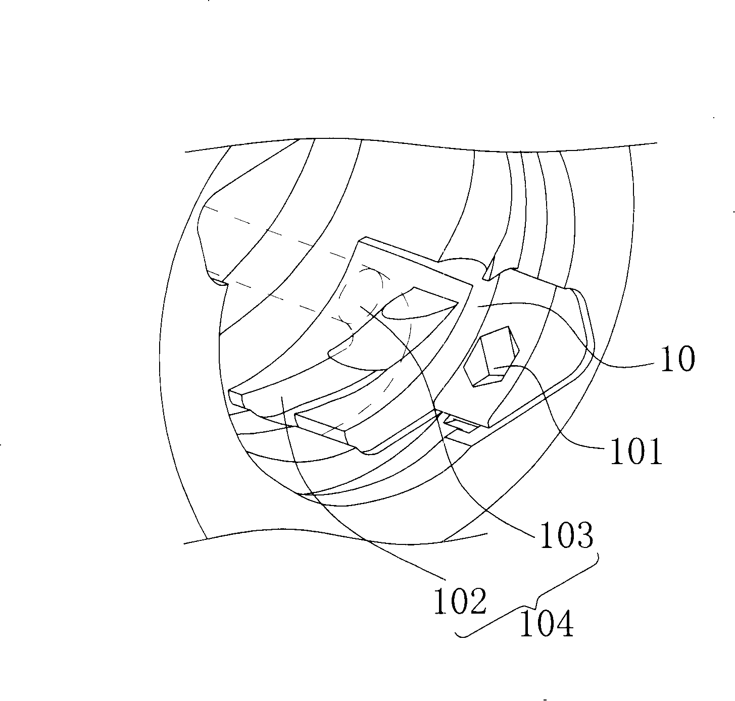
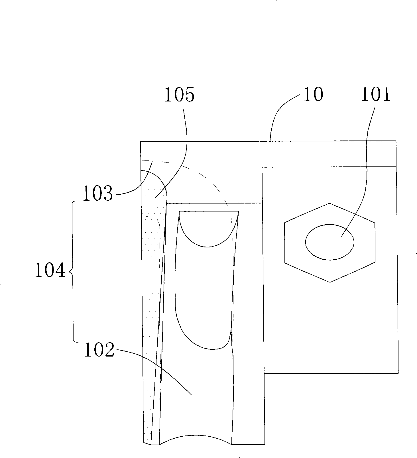
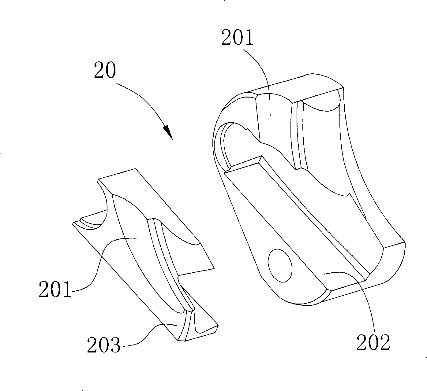
[0035] like Figure 5 to Figure 10 As shown, the return system of the ball screw of the present invention mainly includes: a screw 1, a nut 2, several return components 3 and balls 4; the outer surface of the screw 1 and the inner surface of the nut 2 have a mutual cooperation The spiral track 11, 21, and at least one through hole 22 is provided inside the nut 2, and the through hole 22 is provided with at least one fixing groove 23 on both ends of the nut 2, which is correspondingly fitted with the return component 3; The assembly 3 has a return path 31 and two openings 311, 312 inside, and the openings 311, 312 are respectively connected to the through hole 22 and the spiral track 21 of the nut 2; 11, 21 and the return flow path 31 of the return assembly 3 form an independent circulation structure that enables the balls 4 to circulate; wherein:

[0036] The fixing groove 23 of the nut 2 is axially provided with a section 24 corresponding to the return assembly 3, and the se...


PUM


Abstract

The invention discloses a return system of a ball screw, which is composed of a screw, a nut, several return components and balls; wherein the fixing groove of the nut is provided with a cross-section along the axial direction to provide a corresponding fitting of the return component, And this cross-section is provided with a continuous taper hole to connect with the through hole, and the cross section and the spiral track will not interfere; The shrinkage cavity is nested accordingly; the design of the return component can solve the current problem of the small radius of curvature of the return path and the destruction of the helical track alveolar by the fitting of the fixed groove, so that the radius of curvature of the return path can be increased, thereby improving the circulation of the balls in it smoothness.

Description

technical field [0001] The invention relates to a return system of a ball screw, in particular to a fixed groove with a continuous tapered hole section along the axial direction, providing a convex turning structure of the return assembly and nesting with the section, so that the fixed groove can avoid the spiral track Without interference, while increasing the radius of curvature of the return path of the return system. Background technique [0002] The ball screw is a kind of nut that fits on the screw, and the relative movement is generated by the rolling cycle of the ball between the screw and the opposite inner side of the nut. [0003] In order to make the ball between the screw and the nut turn to the backflow, a backflow assembly is installed on the inner thread of the nut so that the ball can turn to the backflow to form an overall circular rolling. [0004] As far as the current methods of ball screw return flow are concerned, some are the external return flow tha...

Claims


Application Information

Patent Timeline
IPC IPC(8): F16H25/22
Inventor 邹健伟吴文加
Owner HIWIN TECH
Why Eureka
Try Eureka