

Internal-combustion engines vehicle power intelligence control system and control method control method thereof
A technology of intelligent control system and internal combustion engine, applied in transmission control, mechanical equipment, components with teeth, etc., can solve the problem of neglecting the energy-saving technology of the whole vehicle
- Summary
- Abstract
- Description
- Claims
- Application Information
AI Technical Summary
Problems solved by technology
Method used
Image

Examples
Embodiment approach 1
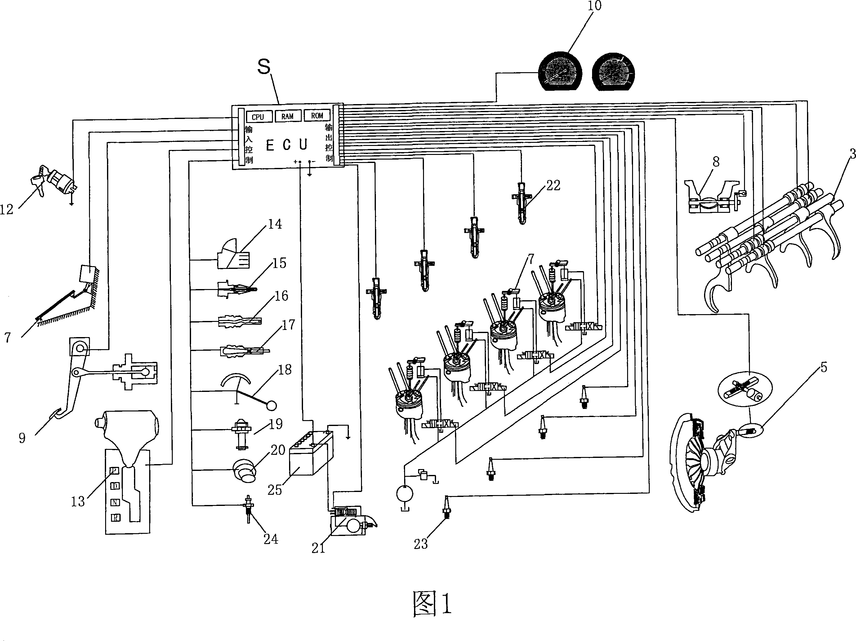
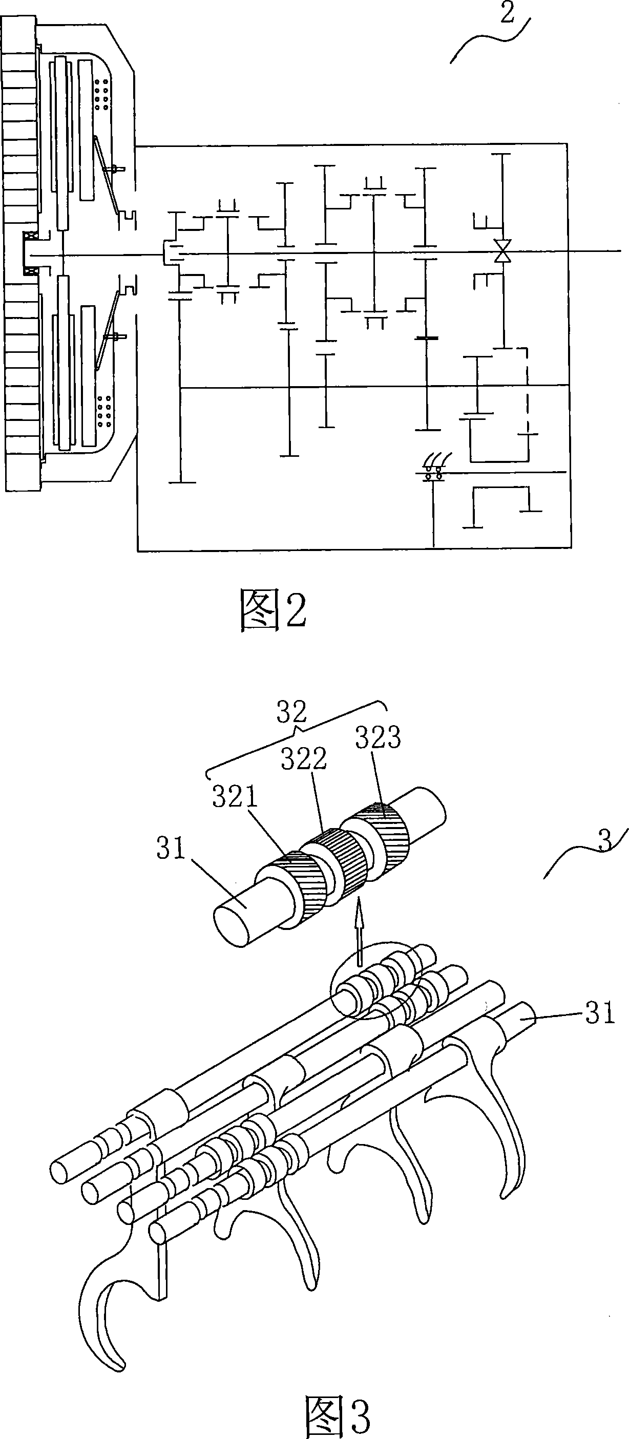
[0043] As shown in Figures 1-3, the internal combustion engine vehicle power intelligent control system that the present invention relates to comprises engine, sensor, speed change device and central controller (ECU), and described central controller S (can be computer) obtains according to sensor The electrical signal matches the speed of the engine with the transmission to realize automatic gear shifting without interrupting the power of the engine. Specifically, the transmission device includes a transmission 2 and a transmission actuator 3. The transmission 2 includes multiple pairs of transmission gears respectively corresponding to each gear. When the driver intends to change gears, the central controller S controls the The speed of the engine is used to control the linear velocity of the pitch circle between the transmission gears corresponding to the driving speed required by the driver to be equal, and in the state that the pitch circle linear velocity between the tran...
Embodiment approach 2
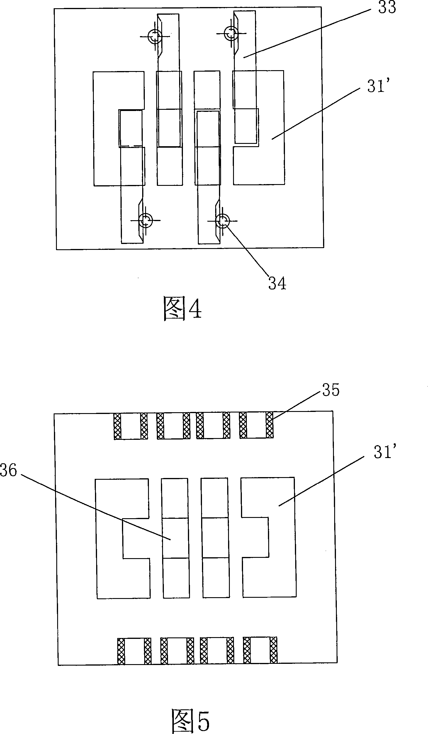
[0077] The transmission actuator in this embodiment is different from that in Embodiment 1. As shown in Figure 4-7C, the transmission actuator in this embodiment includes a plurality of shift fork shafts 31', and each of the shift fork shafts 31' There is a transmission slot 36 on each of the transmission slots 36, and a transmission slider 33 with a boss 331 is correspondingly inserted on each of the transmission slots 36. The central controller controls the dial by controlling the displacement of the transmission slider 33. Displacement of the fork shaft 31'.
[0078] As shown in Fig. 4 and Fig. 6A-6C, at this moment, one end of the transmission slider 33 is connected with a stepper motor 34 and a worm gear mechanism, and the central controller S controls the stepper motor 34, and by means of the worm gear mechanism , to control the displacement of the transmission slide block 33.
[0079] As shown in Fig. 5, Fig. 6A-6C and Fig. 7A-7C, coils 35 are arranged at both ends of ...
Embodiment approach 3
[0082] As shown in Figure 9, the decompression actuator in this embodiment is different from that in Embodiment 1. The decompression actuator in this embodiment includes a fixed electromagnetic coil 45 and a movable electromagnetic coil 46, and the movable electromagnetic coil 46 and A top pressing block 47 is fixedly arranged, and the top pressing block 47 protrudes from the lower surface of the movable electromagnetic coil 46, the pressure reducing valve 41 can slide in the fixed electromagnetic coil 46, and the central controller S controls the electromagnetic coil 45, The current direction of 46 makes the movable electromagnetic coil 46 attracted by the fixed electromagnetic coil 45, and the pressing block 47 pushes the pressure reducing valve 41 downward, thereby realizing the opening of the pressure reducing valve 41, otherwise the closing of the pressure reducing valve 41 can be realized. That is to say, in this embodiment, the central controller controls the opening or ...
PUM
 Abstract
Description
Claims
Application Information