
Stove-fuel flow online control device and method thereof

A fuel flow and control device technology, which is applied in the direction of combustion methods, combustion control, and fuel supply adjustment, and can solve problems such as slow response speed, simple and rough, and furnace blockage

Active Publication Date: 2008-05-21
ZHENHAI PETROCHEMICAL ENG CO LTD
View PDF0 Cites 40 Cited by
  • Summary
  • Abstract
  • Description
  • Claims
  • Application Information

AI Technical Summary

Problems solved by technology

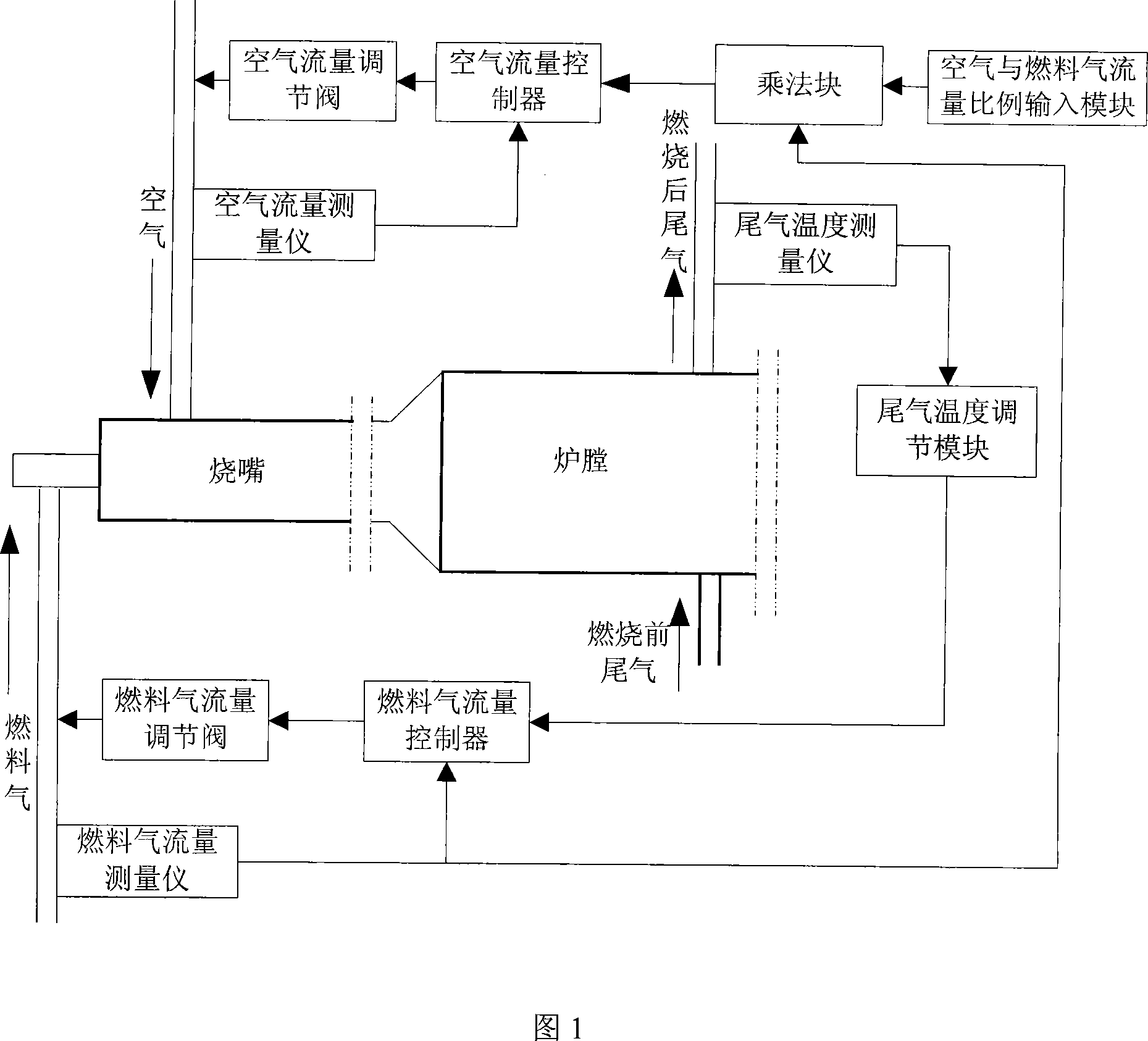
[0004]The above-mentioned method of controlling the fuel flow of the online furnace is relatively simple and rough, and is easily affected by the fluctuation of the external fuel gas or air density, and the consumption of fuel gas is too large, that is, the inflow The density of the fuel gas is not a fixed value. In actual situations, the density of the fuel gas fluctuates up and down within a certain range, but the above control method does not take into account the influence of the fluctuation of the fuel gas density, and the response speed of the control is relatively slow. When changing the input value of the ratio of fuel gas to air flow rate, it will affect the combustion effect of the fuel in the online furnace. Either there is too much air, and the combustion will be overoxygen, or there will be insufficient air, whether it is overoxygen combustion or insufficient combustion, it will affect the online furnace. When the temperature of the online furnace is too high, it will affect the life of the catalyst. When the temperature is too low, carbon deposits are prone to occur, and carbon deposits are likely to block the furnace.

Method used


Image

  • Stove-fuel flow online control device and method thereof
  • Stove-fuel flow online control device and method thereof
  • Stove-fuel flow online control device and method thereof

Examples


Embodiment Construction

[0058] The present invention will be further described in detail below in conjunction with the accompanying drawings and embodiments.

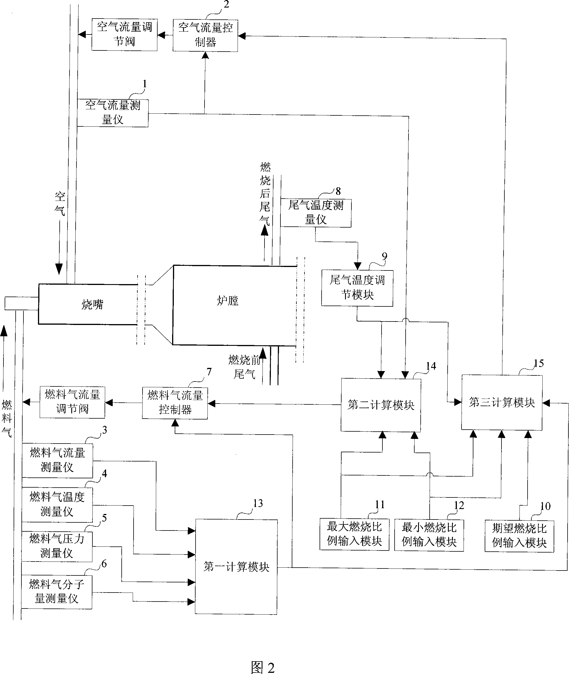
[0059] The online furnace fuel flow control device shown in Figure 2, the online furnace includes a burner and a furnace, the burner is connected to the online furnace air feed pipe and the online furnace fuel gas feed pipe, and the furnace is connected to the online furnace tail gas outlet Tube. Wherein, an air flow measuring instrument 1, an air flow regulating valve and an air flow controller 2 for controlling the air flow regulating valve are arranged on the air feed pipe of the online furnace. The fuel gas flow measuring instrument 3, the fuel gas temperature measuring instrument 4, the fuel gas pressure measuring instrument 5, the fuel gas molecular weight measuring instrument 6, the fuel gas flow regulating valve and the The fuel gas flow controller 7 of the gas flow regulating valve. Exhaust gas temperature measuring instrument 8, ex...


PUM


Abstract

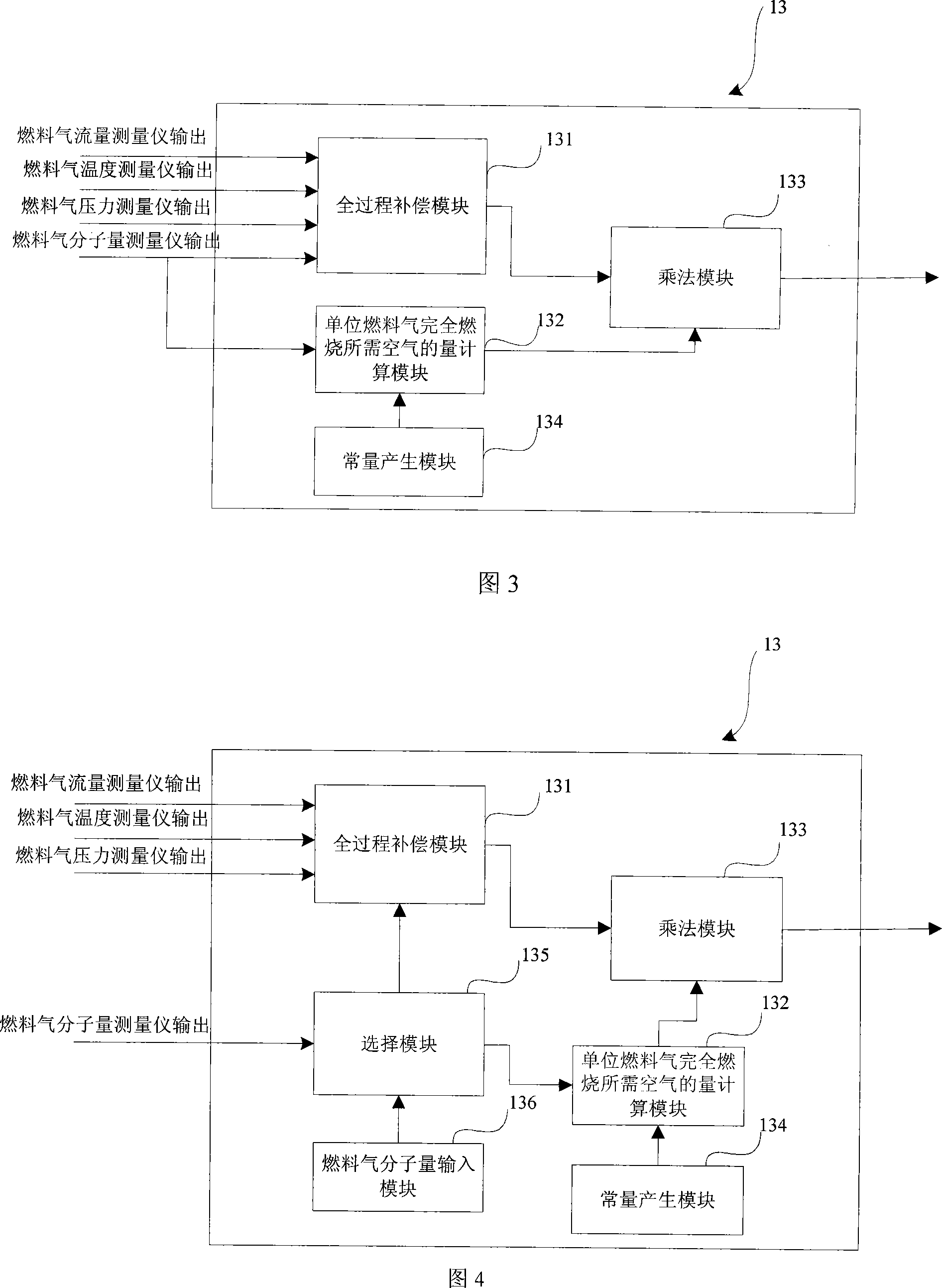
The invention relates to an online furnace fuel flow control device and a method thereof. The device introduces a fuel gas molecular weight measuring instrument, a fuel gas temperature measuring instrument of a fuel gas feeding pipe, and fuel gas pressure measuring instrument parameters and is used for calculation after precision compensation. In the future, the first calculation module for the measured value of the fuel gas flow and the second calculation module for calculating the set value of the fuel gas flow when the real-time ideal combustion effect of the on-line furnace is used will correct and adjust the flow of the fuel gas to ensure that the fuel gas involved in the control The air flow value is the flow rate that can be completely burned. At the same time, the third calculation module is introduced to calculate the air flow setting value of the real-time ideal combustion effect of the online furnace to adjust the air flow flowing into the online furnace, so that the air flow into the online furnace The fuel ratio in the furnace can achieve the ideal combustion effect, ensuring that the temperature of the exhaust gas of the online furnace is at the ideal temperature value.

Description

technical field [0001] The invention relates to an online furnace fuel flow control device and a method thereof. Background technique [0002] In the sulfur production process, there are several ways to heat the tail gas, such as gas-gas blending, steam heating, and online furnace heating. However, the scale of existing sulfur production equipment is getting larger and larger, and the amount of tail gas that needs to be heated is also increasing. Using an online furnace to heat tail gas in the sulfur production process has the advantages of real-time control and the ability to manually adjust the temperature of the tail gas. The application is more and more extensive. [0003] At present, the fuel flow control of industrial online furnaces generally adopts the method of connecting the furnace outlet temperature with the fuel gas flow in series and controlling the ratio of fuel gas and air flow to control the online furnace fuel gas flow and air flow. The control method is s...

Claims


Application Information

Patent Timeline
Patent Type & Authority Applications(China)
IPC IPC(8): F23N5/02F23N5/18F23N1/02
Inventor 王鋆陈奎陈伟东徐玉娟胡伯琪田广曹伟伟
Owner ZHENHAI PETROCHEMICAL ENG CO LTD
Learn More