Light-source with fabric diffusing layer

A light source and fabric technology, applied in the field of diffusion layer, can solve the problems of not disclosing the diffusion effect

Active Publication Date: 2008-05-21
SIGNIFY HLDG BV
View PDF1 Cites 17 Cited by
  • Summary
  • Abstract
  • Description
  • Claims
  • Application Information

AI Technical Summary

Problems solved by technology

[0007] However, this document does not disclose how to use th

Method used


Image

  • Light-source with fabric diffusing layer
  • Light-source with fabric diffusing layer

Examples


no. 1 example

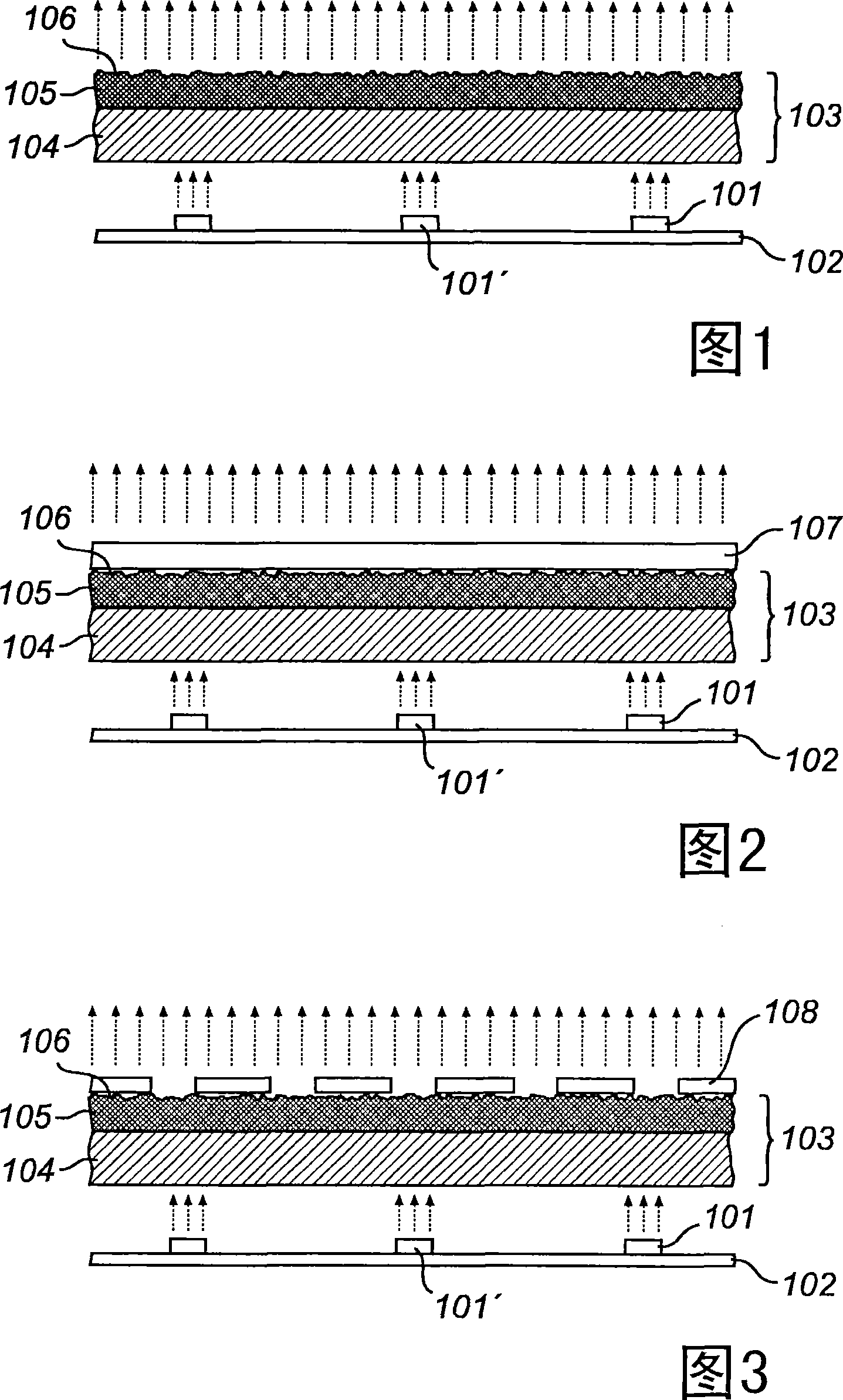
[0033] Fig. 1 shows a first embodiment of a light source according to the present invention, the first embodiment includes an array of light emitting units 101 arranged on a substrate 102, and a light diffuser 103 arranged on the array, wherein each The light emitting unit includes a light emitting diode.

[0034] The light diffuser 103 includes a first layer 104 of low-density non-woven fabric facing the light emitting unit 101 , and a second layer 105 of non-woven fabric with a higher density than the first layer 104 .

[0035] As used herein, the term "light emitting diode" or "LED" refers to a light emitting diode capable of emitting light in a wavelength range from infrared to extreme ultraviolet. The term also refers to all the different kinds of LEDs, including organic-based, polymer-based and inorganic-based LEDs, as well as laser diodes.

[0036] Advantageously, the lighting unit of the invention comprises one or more light emitting diodes. However, other light-emit...


PUM


Abstract

A light-source comprising at least one lighting unit (101) being arranged on a substrate (102) and a diffusing element (103) being arranged to receive and diffuse light emitted by said at least one lighting unit (101) is provided. The diffusing element (103) comprises a layer of non-woven fabric having a lower density at a side facing the lighting unit and a higher density at a side opposite to the lighting unit to obtain good diffusing properties.

Description

technical field [0001] The invention relates to a light source comprising at least one light-emitting unit and a diffusing element, wherein the at least one light-emitting unit is arranged on a substrate, and the diffusing element is arranged to receive and diffuse light emitted by the at least one light-emitting unit of light. The invention also relates to a diffusing layer for being arranged on a light source. Background technique [0002] Large-area luminous textiles will open up new interiors and clothing for a wide range of applications, from lighting to creating atmospheres that convey a message. [0003] LEDs are the main light source candidates for textile integration. However, LEDs are small point sources of light. Multiple LEDs distributed over the surface of the fabric do not illuminate the entire fabric, but only allow a small portion of the fabric covered with the light source to glow. [0004] For many light-emitting textile applications, it is desirable to...

Claims


Application Information

Patent Timeline
IPC IPC(8): G09F13/22G09F9/33
CPCA41D19/0157F21V33/0008A45C15/06A63H3/02A47G11/003A41D27/085A45F3/04A47G9/1045G09F9/33G09F13/22
Inventor S·阿斯瓦蒂M·克兰斯M·P·B·范布吕根J·T·A·维尔德贝克J·M·J·登东德
Owner SIGNIFY HLDG BV
Why Eureka
Try Eureka