Ultrasound wave equipment for breaking milk and removing oil

An ultrasonic and demulsification technology, applied in the field of ultrasonic demulsification and degreasing equipment, can solve the problems of liquid secondary emulsification, affecting the demulsification effect, and difficult to control the strength, so as to achieve uniform separation flow field, convenient operation and maintenance of equipment, and degreasing high efficiency effect

Inactive Publication Date: 2008-05-28
上海阳山材料科技有限公司
View PDF5 Cites 16 Cited by
  • Summary
  • Abstract
  • Description
  • Claims
  • Application Information

AI Technical Summary

Problems solved by technology

However, the above two patents have the following disadvantages: superimposition or focusing occurs between the two ultrasonic waves in the demulsification chamber, the intensity is not easy to control, and may even cause secondary emulsification of the treated liquid; the ultrasonic demulsification device is ins

Method used


Image

  • Ultrasound wave equipment for breaking milk and removing oil

Examples


Embodiment 1

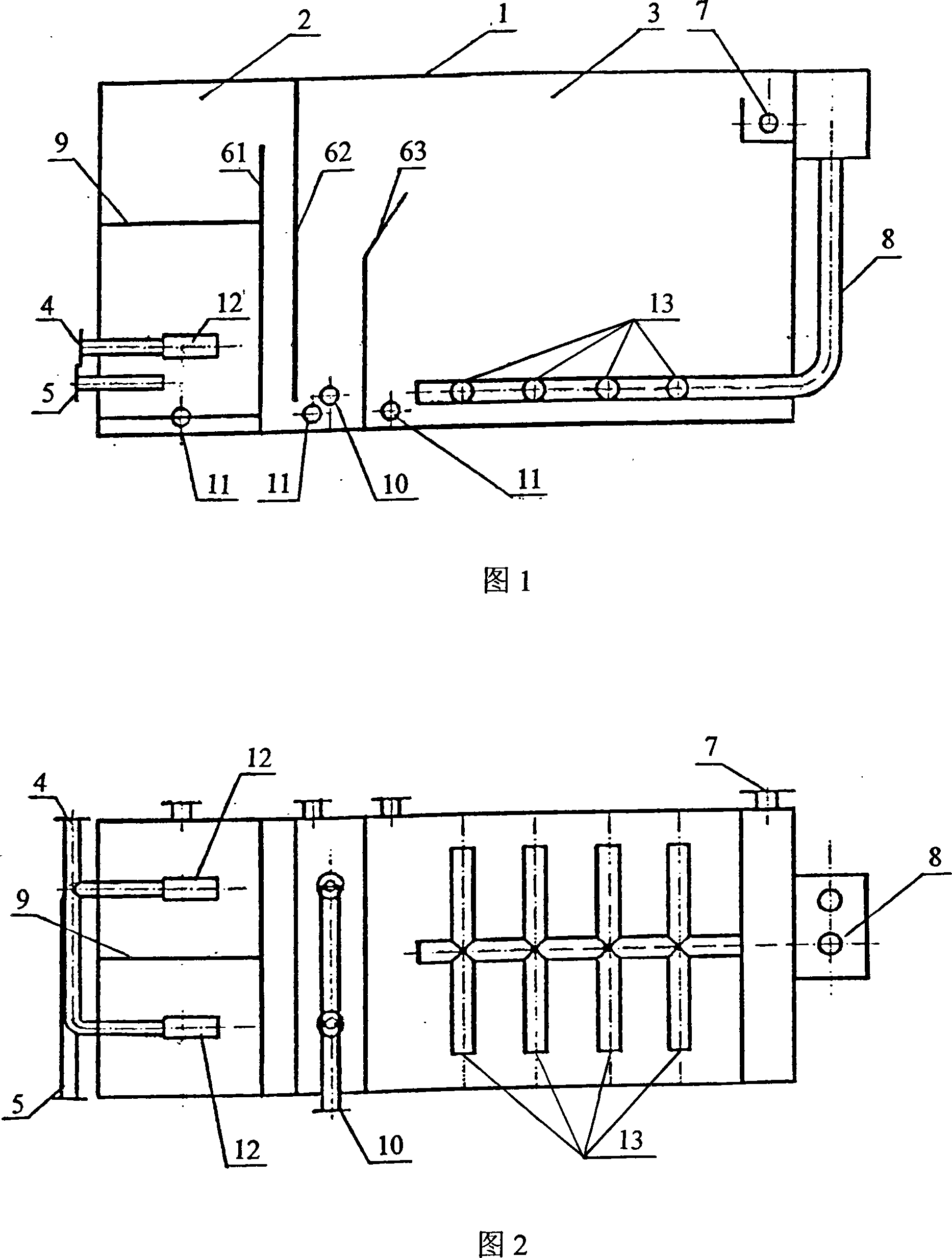
[0019] As shown in Figures 1 and 2, an ultrasonic demulsification and degreasing equipment includes a housing 1, an ultrasonic demulsification chamber 2, and an air flotation separation chamber 3. The housing 1 is provided with an air inlet pipe 4 and a water inlet pipe. 5. Dissolved air water inlet 10, water outlet pipe 8, oil outlet 7, and sewage outlet 11. The ultrasonic demulsification chamber 2 and the air flotation separation chamber 3 are separated by three partitions 61, 62, and 63. The water inlet pipe 5 enters from the lower part of the ultrasonic demulsification chamber 2, the water outlet pipe 8 is arranged at the lower part of the air flotation separation chamber 3, and the part of the water outlet pipe 8 located at the lower part of the air flotation separation chamber 3 includes a plurality of evenly distributed Water outlet 13, described ultrasonic demulsification chamber 2 is provided with two ultrasonic generators 12, and these two ultrasonic generators 12 com...

Embodiment 2

[0021] Referring to Fig. 1 and Fig. 2, an ultrasonic demulsification and degreasing equipment includes a housing 1, an ultrasonic demulsification chamber 2, and an air flotation separation chamber 3. The housing 1 is provided with an air inlet pipe 4, a water inlet pipe 5, Dissolved air water inlet 10, water outlet pipe 8, oil outlet 7, and sewage outlet 11. The ultrasonic demulsification chamber 2 and the air flotation separation chamber 3 are separated by three partitions 61, 62, 63. The inlet The water pipe 5 leads into the lower part of the ultrasonic demulsification chamber 2, the water outlet pipe 8 is arranged at the lower part of the air flotation separation chamber 3, and the part of the water outlet pipe 8 located at the lower part of the air flotation separation chamber 3 includes a plurality of evenly distributed water outlets 13. The ultrasonic demulsification chamber 2 is provided with two ultrasonic generators 12, the two ultrasonic generators 12 include oscillat...


PUM


Abstract

The invention relates to an equipment breaking emulsion and removing oil by ultrasonic, comprising a shell body, an ultrasonic emulsion breaking chamber and an air floatation separation chamber. The shell body is provided with an air inlet pipe, a water inlet pipe, a dissolved water inlet, a water outlet pipe, an oil outlet and a sewage outlet. The ultrasonic emulsion breaking chamber and the air floatation separation chamber are formed by the separation of a plurality of clapboards. The ultrasonic emulsion breaking chamber is provided with at least two ultrasonic generators. The ultrasonic emulsion breaking chamber is provided with an isolation board which at least separates two ultrasonic generators. The ultrasonic generators are arranged between the distance of 1/4 to 1/2 to the bottom of the ultrasonic demulsification chamber. The water outlet pipe is arranged on the lower part of the air floatation chamber. Compared with the prior art, the equipment of the invention for breaking emulsion and removing oil is simple in structure and high in oil removal efficiency, which completely solves the problem of secondary emulsification caused by mutual interference and mutual superposition among ultrasonic. The invention is uniform and easy in flow field separation, low in energy consumption, easy in operation and convenient in operation and maintenance.

Description

technical field [0001] The invention relates to an oil-water separation device, in particular to an ultrasonic demulsification and oil removal device. Background technique [0002] In the sewage treatment process, an important process is oil-water separation, or degreasing. The key to oil-water separation is to try to break the original water-in-oil and oil-in-water emulsification structure with tight combination and different specifications. This process is called demulsification. Sedimentation etc. to separate oil and water. At present, in addition to the commonly used chemical demulsification in industrial production, that is, the demulsification process is achieved by adding a chemical demulsifier to the emulsion, the cavitation effect generated by ultrasonic waves is also used to achieve demulsification. This method has been considered as a new method. An effective demulsification method. [0003] CN2296230 discloses a "ultrasonic demulsification device for electric ...

Claims


Application Information

Patent Timeline
IPC IPC(8): B01D17/04
Inventor 蒋士忠蒋勤新
Owner 上海阳山材料科技有限公司
Why Eureka
Try Eureka