Cyclone separating gas oil separator

An oil and gas separator and cyclone separation technology, applied in separation methods, dispersed particle separation, cyclone devices, etc., can solve the problems of pump oil splashing, large airflow resistance, oil-line spraying, etc., and achieve good oil and gas separation effect, Reasonable structure design and small airflow resistance

Inactive Publication Date: 2008-05-28
蔡海涛 +1
View PDF0 Cites 7 Cited by
  • Summary
  • Abstract
  • Description
  • Claims
  • Application Information

AI Technical Summary

Problems solved by technology

When the oil-sealed rotary mechanical vacuum pump pumps the atmosphere with the air inlet open, or the air inlet pressure is high (greater than 1.3×10 3 Pa) When working continuously for a long time, the airflow rushes out of the exhaust port at a speed of 18-24 m / s. The high-speed airflow makes the pump oil in the fuel tank splash. At the same time, the pressure in the fuel tank is relatively high. The high-speed airflow carries the splash The oil droplets are sprayed out from the exhaust port, and in severe cases, they are sprayed into oil lines, causing environmental pollution and rapid consumption of pump oil, especially for large and medium-sized pumps and high-speed direct-coupled pumps.
[0004] In order to solve the above oil injection problems of oil-sealed rotary mechanical vacuum pumps, the following technical measures are usually taken at present: 1. Increase the volume of the oil tank as much as possible to reduce the relative pressure in the oil tank and slow down the airflow velocity of the exhaust, but increase the volume of the oil tank At the same time, the volume and weight of the pump are increased, and the fuel injection problem is not fundamentally solved; 2. Additional devices such as oil deflectors and oil filter screens, when the high-speed air flow carrying oil droplets passes through these devices, although the above devices will block Or filter part of the oil droplets, but the high-speed airflow will also take away some of the oil droplets on these devices at the same time, and the airflow resistance is large; 3. Add an oil-gas separator. The conventional oil-gas separator has filter screens or adsorption fillers, and the structure is complex , inconvenient maintenance, and large airflow resistance

Method used


Image

  • Cyclone separating gas oil separator

Examples


Embodiment Construction

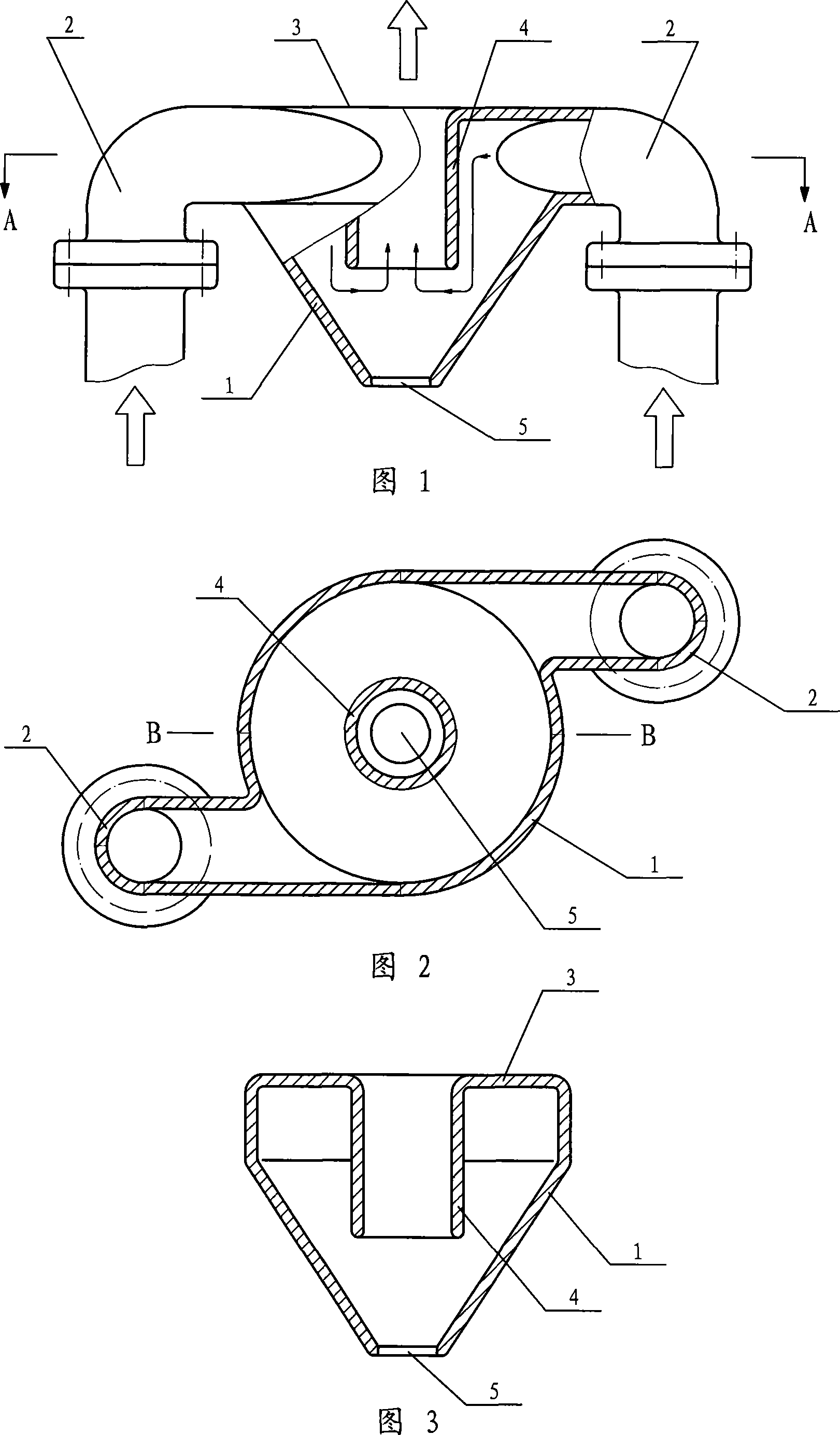
[0016] As shown in the figure, the cyclone oil-gas separator is composed of a shell 1, a top cover 3 connected to the top of the shell, and a conduit 2 connected to the upper part of the shell. The conduit 2 is a 90-degree elbow, with Two, symmetrically installed on the housing 1, the housing 1 is in the shape of a truncated cone, the upper part is larger and the lower part is smaller. The center of the top cover 3 is connected with a central exhaust pipe 4 which is integrated with it. The central exhaust pipe 4 is located at the center of the housing 1, and the bottom of the housing 1 has an oil outlet 5 located below the central exhaust pipe. , the air outlet of the transverse part of the duct 2 is tangent to the inner wall of the upper part of the housing, the air inlet of the central exhaust pipe 4 is lower than the air outlet of the duct 2, and the air outlet of the central exhaust pipe 4 is flush with the outer wall of the top cover 3 . The vertical part of the conduit ...


PUM


Abstract

The invention discloses an oil-gas separator used in an oil-sealing type rotating mechanical vacuum pump. The conventional oil-gas separators which are all internally provided with filter screens and absorption fillers, have the disadvantages of complex structure, inconvenient maintenance, big airflow resistance and small treatment capacity. The invention comprises a shell body and a catheter which is connected with the upper part of the shell body, the invention is characterized in that the top part of the shell body is provided with a coping which is connected with a central exhaust pipe arranged in the center of the shell body; the bottom of the shell body is opened with an oil exit pore positioned below the central exhaust pipe; the air outlet of the catheter is tangent to the inner wall on the upper part of the shell body. The invention leads the air in the separator to have longer path and has the advantages of good separation effect, small airflow resistance, large treatment capacity and convenient maintenance.

Description

technical field [0001] The invention relates to parts in mechanical vacuum pumps, in particular to an oil-gas separator used in oil-sealed rotary mechanical vacuum pumps. Background technique [0002] Both the slide valve vacuum pump and the rotary vane vacuum pump are oil-sealed rotary mechanical vacuum pumps. Because of their direct exhaust to the atmosphere, they can be used alone or as the backing pump of high vacuum units. The most widely used pumps are widely used in chemical industry, metallurgy, military industry, scientific research, light industry, medicine and other fields. [0003] The working medium used in the oil-sealed rotary mechanical vacuum pump is mechanical vacuum pump oil, which is used to seal, lubricate and fill the various moving and non-moving gaps of the vacuum pump. For this reason, oil-sealed rotary mechanical vacuum pumps are equipped with devices such as oil tanks, oil passages, oil retainers, oil filters or oil-gas separators. When the oil-s...

Claims


Application Information

Patent Timeline
Patent Type & Authority Applications(China)
IPC IPC(8): B04C5/00B01D45/16
Inventor 蔡海涛裘旭东
Owner 蔡海涛
Why Eureka
Try Eureka