
Mechanical defoaming device

A defoamer and mechanical technology, which is applied in the direction of paper machine, paper machine wet end, textile and paper making, etc., can solve the problems of long-term idle use, etc., and achieve the effect of reliable operation, easy operation and maintenance, and compact structure

Inactive Publication Date: 2008-05-28
YUEYANG FOREST & PAPER CO LTD
View PDF0 Cites 7 Cited by
  • Summary
  • Abstract
  • Description
  • Claims
  • Application Information

AI Technical Summary

Problems solved by technology

Therefore, such a defoamer is actually useless, and there is no difference between installing it or not. Many factories have not installed it at all, or have left it idle for a long time.

Method used


Image

  • Mechanical defoaming device

Examples


Embodiment Construction

[0013] Below according to accompanying drawing and specific embodiment the present invention is further described as follows:

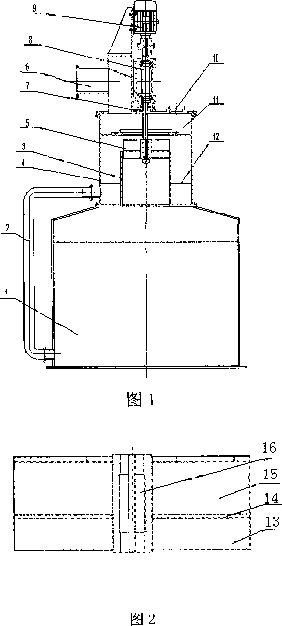
[0014] As can be seen from Fig. 1, the mechanical defoamer of the present invention includes a motor 9, a main shaft 8, an impeller 5, and an exhaust port 6, and is placed on the foam collection tank 1, forming a combination with the foam collection tank 1, and the suction of the defoamer The mouth is a vertical diversion inner cylinder 3, its diameter can contain the impeller 5, and the diversion inner cylinder outside is the diversion outer cylinder 4 that constitutes the housing of the defoamer. A trapping chamber 12 is formed between the flow-guiding inner cylinder 3 and the flow-guiding outer cylinder 4 . An expansion chamber 11 is provided on the guide outer cylinder 4 . There is a discharge port on the diversion outer cylinder 3, which is connected with the foam collection tank 1 through the return pipe 2. As can be seen from Fig. 2, the impe...


PUM


Abstract

The invention discloses a mechanical defoaming device, which comprises a motor (9), a main shaft (8), a turbine wheel (5), and an exhaust hole (6). The invention is characterized in that the device is also provided with a flow guide inside cylinder (3) and a flow guide outside cylinder (4), wherein the flow guide inside cylinder (3) and the flow guide outside cylinder (4) form a capture chamber (12); the turbine wheel is a co-shaft double-layer structure and the down turbine wheel (13) is inside the flow guide inside cylinder (3) and the upper turbine wheel (15) is in the flow guide outside cylinder (4). The device adopts the induced separate defoaming with high capture rate and can realize the absolute defoaming and needs no defoaming agent without any environment pollution and has compact structure, reliable operation and simple maintenance.

Description

1. Technical field: [0001] The invention relates to a mechanical defoaming device, which can be widely used for eliminating foam in industrial production, and is especially suitable for the environment where the black liquor of pulp and paper making is easy to foam. 2. Technical background: [0002] The black liquor produced in the process of pulping and papermaking contains a large amount of saponified substances, which can easily generate foam when disturbed or in contact with air, which seriously pollutes the production environment and causes the loss of valuable resources. It is a major technical problem for enterprises to achieve clean production. There is no mature equipment for effective foam treatment in China. Most of them simply install an agitator with an impeller on the top of the defoaming tank. When the impeller rotates to stir the foam, the foam cannot be broken under the action of the impeller alone. , so that the air in the foam is separated, but a hole is c...

Claims


Application Information

Patent Timeline
IPC IPC(8): D21F1/54
Inventor 周海东张栋基郭勇为陈金山涂陆军
Owner YUEYANG FOREST & PAPER CO LTD
Learn More