

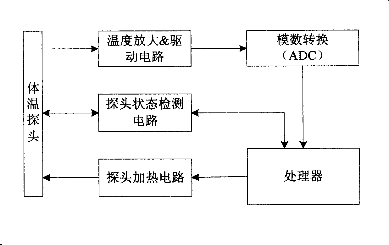
Probe heating circuit of quick body temperature measuring device
A technology for measuring devices and heating circuits, applied in measuring devices, measuring heat, electric heating devices, etc., can solve the problems of lack of safety guarantee, single heating and control function, and failure to meet safety requirements, so as to achieve the goal of improving safety Effect
- Summary
- Abstract
- Description
- Claims
- Application Information
AI Technical Summary
Problems solved by technology
Method used
Image

Examples
Embodiment 1
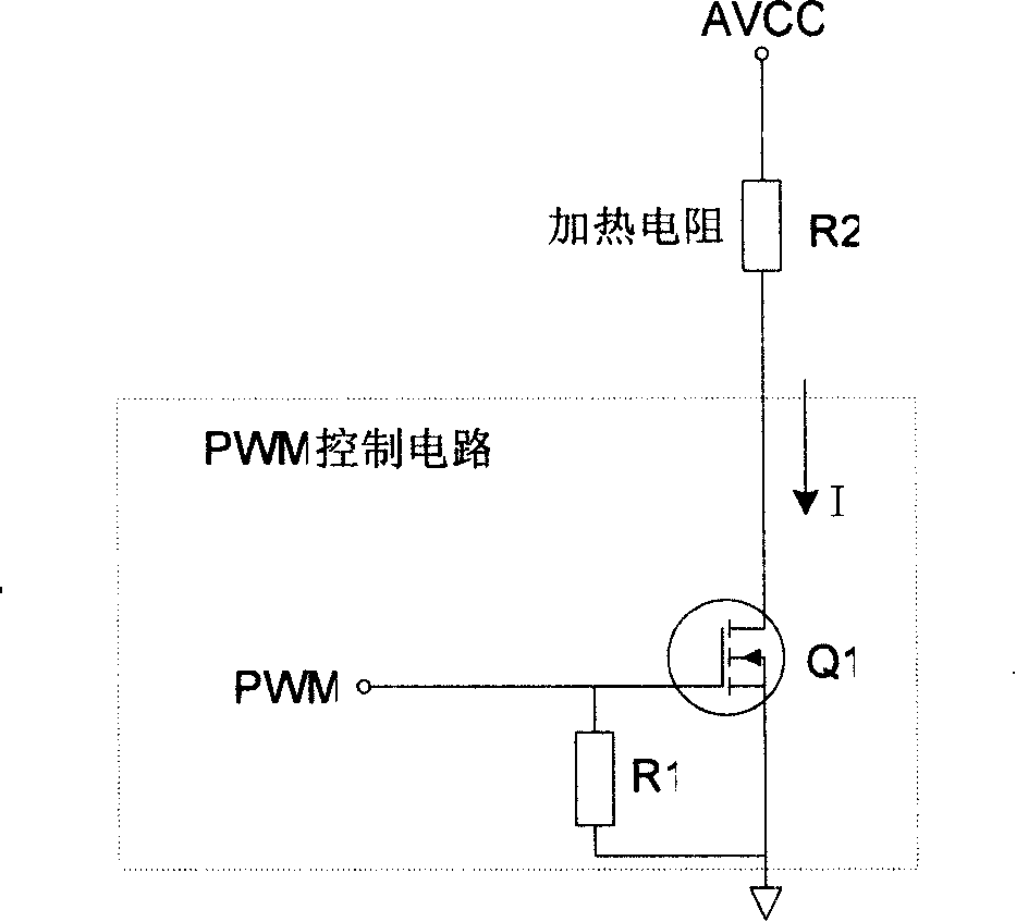
[0047] Embodiment one, as Figure 4 Shown is the probe heating circuit for the heating energy control module to realize the overtime protection function. The heating energy control module includes the overtime protection circuit 3, and the processor is embedded in the probe of the body temperature module to generate the driving switch circuit between on and off modes. The PWM control signal switched between, that is, the signal 1 in the figure, it can control the output power of the probe heater by changing the PWM duty cycle. The heating unit is the heating resistor R2 in the figure. In this embodiment, the switch circuit is a switch circuit K2 connected in series between the heating resistor R2 and the ground.
[0048] There are two kinds of power supplies in this embodiment: one is the heating power supply AVCC, which is specially used for the heater, and is generally 5V; the other is the digital part power supply VDD, which is generally 3.3V, which is used for the power s...
Embodiment 2
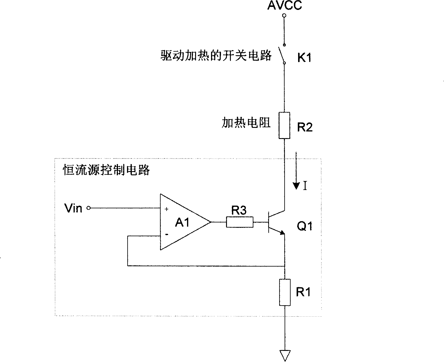
[0060] Embodiment 2. The difference from Embodiment 1 is that the heating energy control module controls the heat provided to the heating resistor through current limiting. The principle of current limiting in this embodiment is: the heater power supply AVCC is connected with a short-circuit limiter for the probe. current protection circuit, and the controllable switch circuit used to connect the current loop of the heating unit is connected between the current limiting protection circuit and the heating unit, and the switch state of the switching circuit is determined by the PWM control signal output by the processor and the output of the current limiting protection circuit The signals are jointly controlled, and only when the two control signals are valid at the same time, the switch circuit will be completely turned on to connect the current loop of the heating unit, so that the heating unit will generate heat to heat up the probe. The current limiting protection circuit can...
Embodiment 3
[0064] Embodiment 3, as shown in Figure 6, on the basis of the above embodiment, a probe heating circuit with a fault detection function is added, and the fault detection circuit 2 is used to monitor the current state of the heater channel, and output a corresponding signal to the processor after a fault is found system for related operations, such as alarming and turning off heaters, etc. The fault detection circuit 2 can be a follower or a comparator. In FIG. 6, the operational amplifier A1 is connected as a follower, the positive input terminal of the operational amplifier A1 is connected to the second terminal of the current limiting resistor R3, and the voltage value at this point is sampled, and the output Signal 3, signal 3 is sent to the ADC input port of the embedded processor for sampling and monitoring heater status: when the heating circuit is normal, the voltage of signal 3 is less than AVCC-U eb0 ; When the heating circuit is short-circuited, the signal 3 voltage...
PUM
 Abstract
Description
Claims
Application Information