Injection appliance and method

A technology for an injection device and a holding device, which is applied in the directions of syringes, hypodermic injection devices, medical science, etc., can solve the problems of stretching, injury and occupation of surrounding tissues, and achieve the effect of improving operation safety.

Inactive Publication Date: 2008-05-28
INNOVACELL BIOTECHNOLOGIE GMBH
View PDF1 Cites 0 Cited by
  • Summary
  • Abstract
  • Description
  • Claims
  • Application Information

AI Technical Summary

Problems solved by technology

However, such an embodiment may be disadvantageous because the sonic or MRI probes occupy space in the body cavity or corresponding body volume, which may lead to stretching of the surrounding tissue and pose a potential risk of injury

Method used


Image

  • Injection appliance and method
  • Injection appliance and method
  • Injection appliance and method

Examples


Embodiment Construction

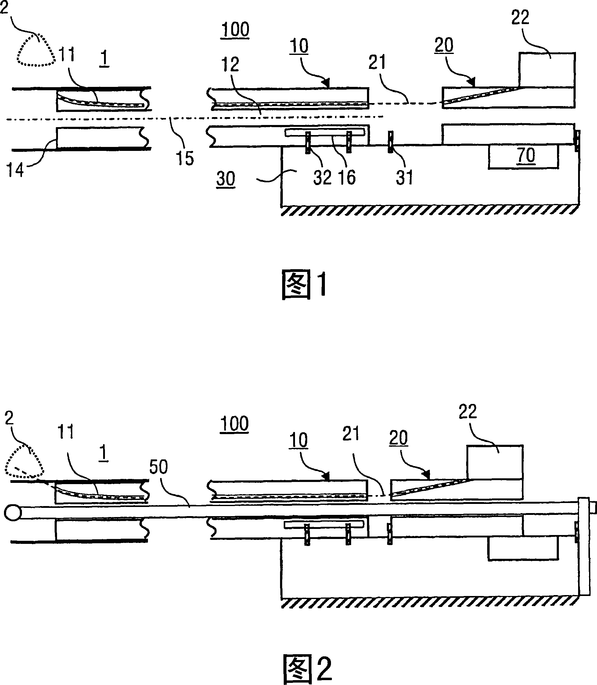
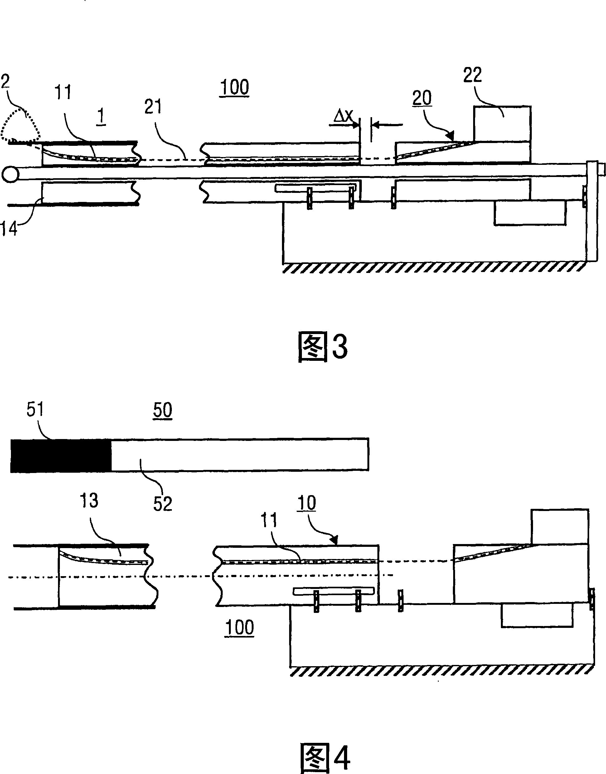
[0032] FIG. 1 shows an example of a first exemplary embodiment of an injection device 100 according to the invention in a schematic sectional view. The injection device 100 includes a guide device 10 , a moving device 20 and a holding device 30 . Reference numeral 70 in FIG. 1 schematically designates a sensing device that can be used to detect the position of the guide device 10 and the displacement device 20 relative to the holding device 30 . The sensor device 70 includes, for example, an optical sensor, by means of which strip-shaped markings on the guide and / or displacement device can be detected.

[0033] The guide 10 is a straight rigid tube with a cavity 11 and a channel 12 . The tube has, for example, a semi-cylindrical shape with one flattened side. The cavity 11 is for receiving an injection tool 21 (shown in phantom) and is angled at an outlet end 14 of the guide 10 to the centerline 15 of the guide 10 . In the illustrated embodiment, channel 12 is used to house...


PUM


Abstract

An injection device (100) for injecting a substance into an organism (1) is described, comprising a guide device (10) with a cavity (11), a movement device (20) connected to an injection tool (21) ), and a holding device (30) forming a support for the guiding and moving device (10, 20), wherein the injection tool (21) is movably arranged in the cavity (11), the guiding And the moving device (10, 20) is movably arranged on the holding device (30). Also disclosed is a method for injecting a substance into an organism (1).

Description

technical field [0001] The invention relates to an injection device for injecting a substance into an organism, having the features of the preamble of claim 1, in particular to an injection device for the targeted injection of a curative substance at a predetermined injection site Injection device into the tissue of the organism. The invention also relates to an injection method using the injection device. Background technique [0002] EP 1 337 183 discloses a medical manipulation device by means of which an injection needle can be introduced into the tissue to be treated. At the outlet end of the manipulator, the injection needle is deflected at an exit angle relative to the axis of the manipulator. The penetration depth of the injection needle into the tissue depends on the protruding length of the tip of the injection needle relative to the outlet end of the manipulation device. In the prior art, an ultrasonic (wave) probe is used to monitor the positioning and injecti...

Claims


Application Information

Patent Timeline
Patent Type & Authority Applications(China)
IPC IPC(8): A61M5/32A61M5/46
CPCA61B5/055A61M5/46A61B8/12A61M5/3287A61M5/178
Inventor R·马克施泰纳
Owner INNOVACELL BIOTECHNOLOGIE GMBH
Why Eureka
Try Eureka