Fluid drop ejection

A fluid injection and fluid technology, applied in the direction of injection devices, printing, single handheld devices, etc., can solve the problems of limited effectiveness and achieve the effects of increasing system processing capacity, reducing maintenance downtime, and reducing ink waste

Active Publication Date: 2008-05-28
FUJIFILM DIMATIX
View PDF10 Cites 10 Cited by
  • Summary
  • Abstract
  • Description
  • Claims
  • Application Information

AI Technical Summary

Problems solved by technology

Therefore, the effectiveness of the pressure ink cleaning method to remove air bubbles is fundamentally limited

Method used


Image

  • Fluid drop ejection
  • Fluid drop ejection

Examples


Embodiment Construction

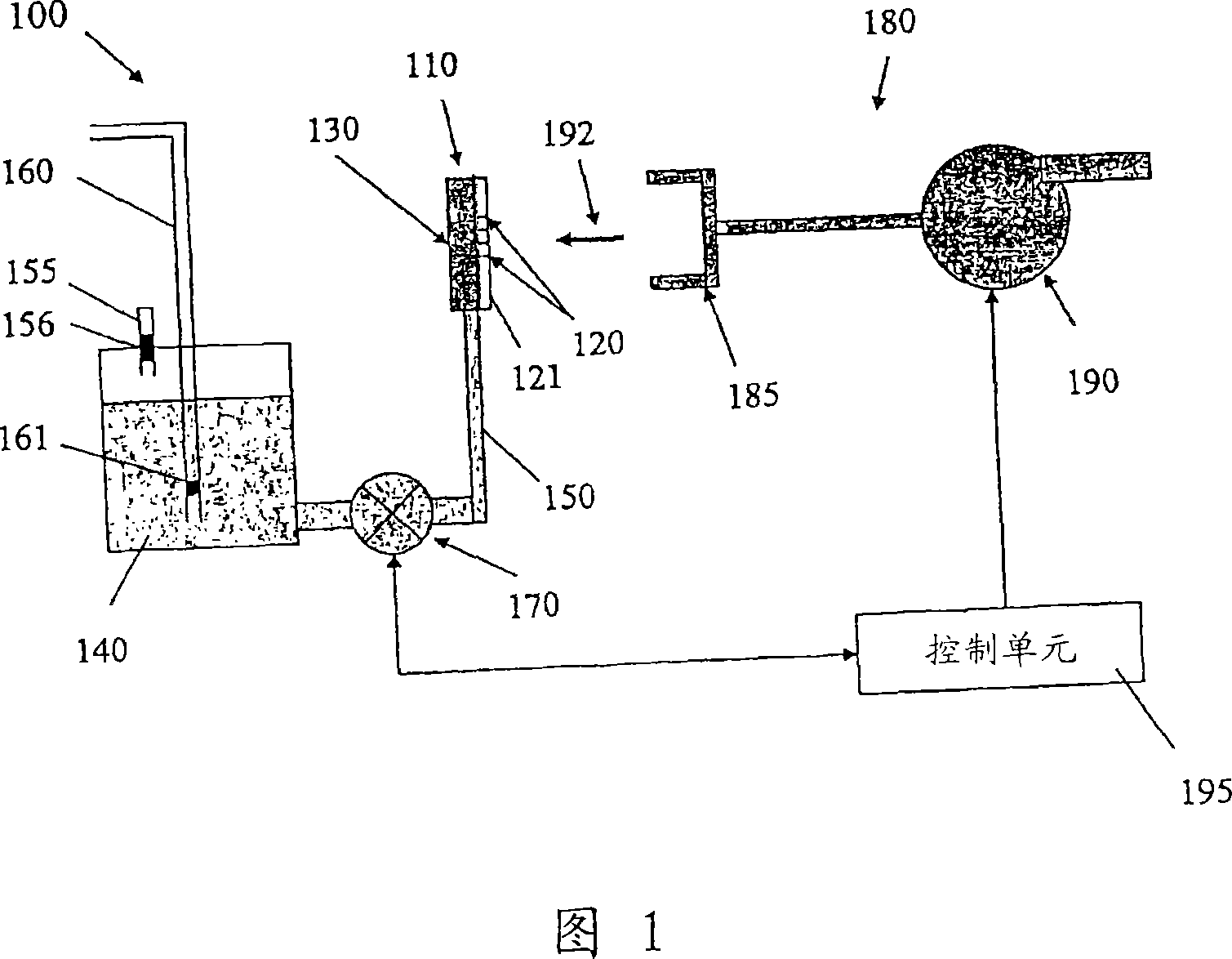
[0020] As shown in FIG. 1 , an inkjet printing system 100 includes an inkjet printhead module 110 having a plurality of ink nozzles 120 arranged generally in an array on a nozzle plate 121, a pumping chamber 130 that supplies ink to the nozzles 120, a reservoir An ink reservoir 140 for ink to be supplied to the pumping chamber 130 and an ink channel 150 for fluid communication between the ink reservoir 140 and the pumping chamber 130 . During printing, ink droplets are ejected from the ink nozzles 120 in response to input image data to form an image ink dot pattern on the ink receiver.

[0021] Inkjet printhead module 110 may be in the form of piezoelectric inkjet, thermal inkjet, MEMS inkjet based printheads, and other types of ink actuation mechanisms. For example, US 5,265,315 to Hoisington et al., the entire content of which is hereby incorporated by reference, describes a printhead having a semiconductor printhead body and piezoelectric actuators. The printhead body is c...


PUM


Abstract

A drop ejection system includes a flow regulator that can regulate the fluid flow to enhance fluid purging from the fluid ejection head and other system operations. The drop ejection system can include a drop ejection head with a plurality of nozzles, a pumping chamber, and a fluid purge unit capable of purging the fluid from the nozzles by generating a negative pressure outside of nozzles. The flow regulator can increases the flow resistance of the fluid flow to the drop ejection head when the fluid is purged out of the nozzles.

Description

technical field [0001] This application relates to the field of droplet ejection. Background technique [0002] In many inkjet systems, a piezoelectric crystal having a pressure-generating surface in communication with a channel is usually used to apply successive cycles of decreasing and increasing pressure to the ink in the channel, thereby providing the ink with a drop-by-drop pattern. Chambers or channels connected by pores of ink. If the ink introduced into the channel contains dissolved air, the depressurization of the ink during the pressure reducing portion of the pressure cycle will cause the dissolved air to form small bubbles in the ink within the channel. Repeated depressurization of the ink in the chamber causes these air bubbles to grow, and these air bubbles may lead to malfunction of the inkjet device. Also, air bubbles can be introduced into the ink channels by suction at the nozzles, flowing in from a reservoir or canister as the ink temperature cycles du...

Claims


Application Information

Patent Timeline
Patent Type & Authority Applications(China)
IPC IPC(8): B41J2/17
CPCB41J2/1707B41J2/19B05B11/06B41J2/14201B41J2/165B41J2/1652B41J2/2142
Inventor 保罗·A·霍伊辛顿
Owner FUJIFILM DIMATIX
Why Eureka
Try Eureka