Supply pump

A technology for supplying pumps and plungers, used in fuel injection pumps, engine components, machines/engines, etc., to solve problems such as burns

Inactive Publication Date: 2008-06-04
DENSO CORP
View PDF2 Cites 4 Cited by
  • Summary
  • Abstract
  • Description
  • Claims
  • Application Information

AI Technical Summary

Problems solved by technology

[0003] In this conventional charge pump, burns due to sliding friction between the outer peripheral surface of the plunger and the inner peripheral surface

Method used


Image

  • Supply pump
  • Supply pump

Examples


Embodiment Construction

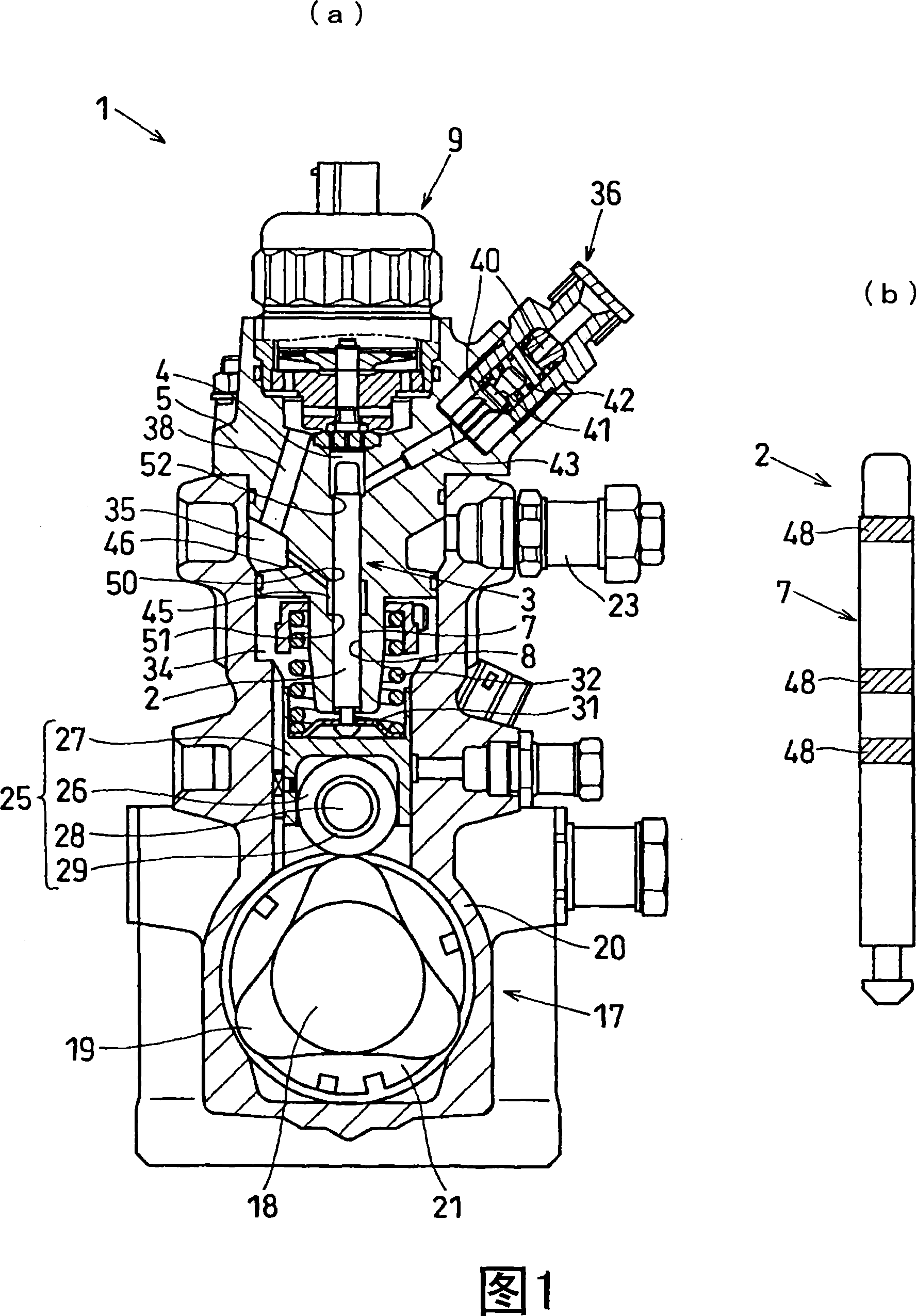
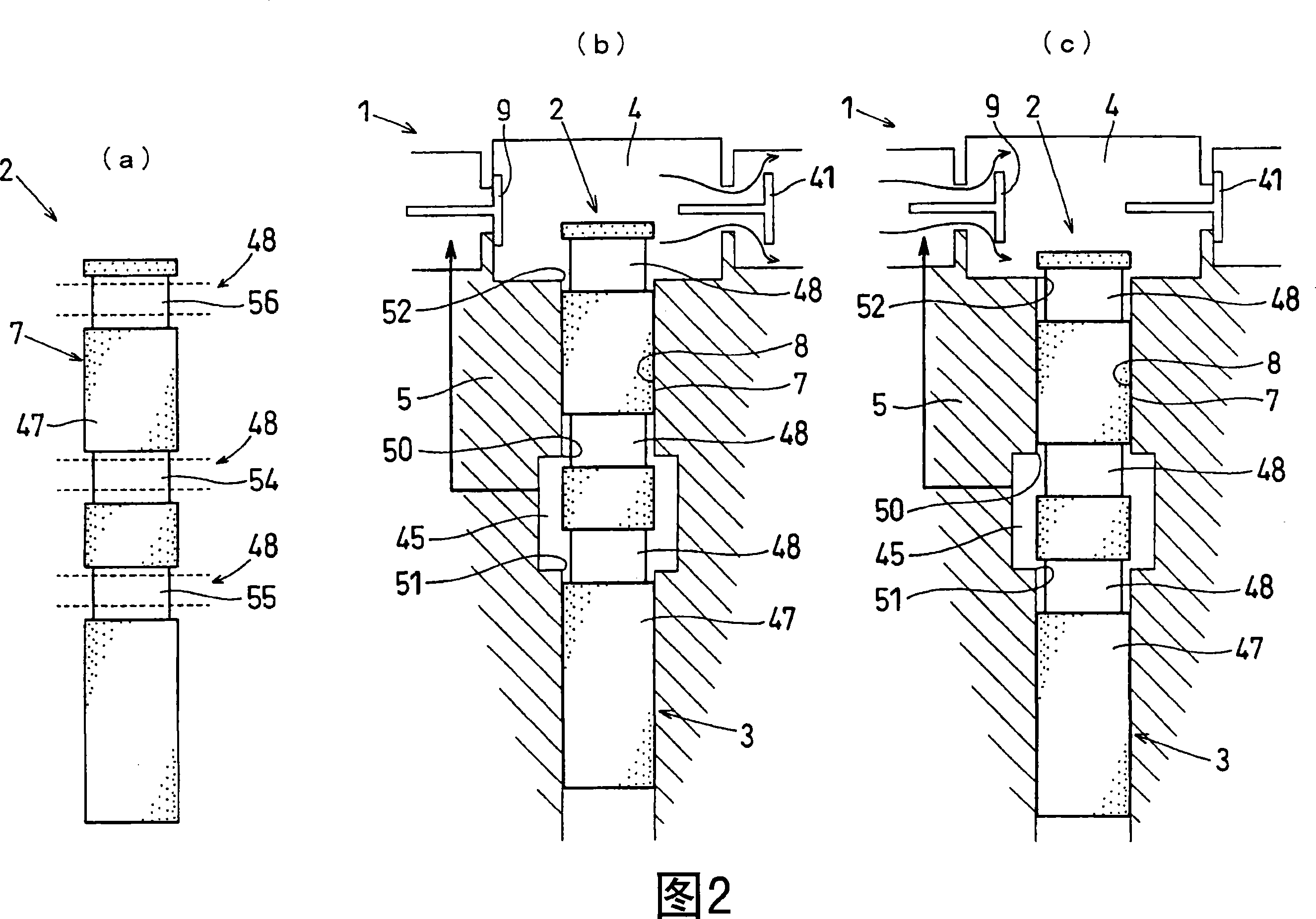
[0021] [Structure of the embodiment]

[0022] The structure of the supply pump 1 of an embodiment is demonstrated using FIG.1 and FIG.2.

[0023] The supply pump 1 is provided with a plunger 2 that is moved up and down in the axial direction by applying a driving force from a predetermined drive source, and a cylinder 3 that accommodates the plunger 2 in an axially slidable manner, and uses the upper part of the cylinder 3 as a pressurized pump for fuel. The cylinder 5 of the chamber 4 sucks fuel into the pressurized chamber 4 in response to the vertical movement of the plunger 2 and discharges the fuel in the pressurized chamber 4 under pressure.

[0024] In addition, the discharged fuel is supplied to, for example, a common rail (not shown) to accumulate pressure in a high-pressure state, and is supplied from the common rail to an injector (not shown) to be injected into a cylinder of an engine (not shown). Inside. In addition, drive control of the supply pump 1, injectors...


PUM


Abstract

The present invention provides a supply pump (1), in the supply pump (1), on the outer peripheral surface (7) subjected to coating treatment, a non-treatment part ( 48). The non-processing part (48) is arranged such that it includes a groove upper edge sliding contact portion (54) that is in sliding contact with the upper edge (50) of the groove (45), a groove that is in sliding contact with the lower edge (51) of the groove (45). At least one of the groove lower edge sliding contact portion (55) and the pressurization chamber lower edge sliding contact portion (56) slidingly contacting the lower edge (52) of the pressurization chamber (4). Thereby, the surface region with a high possibility of burn can be recessed with respect to the surface of the coating (47). Therefore, irrespective of the action of external force, the burn resistance of the outer peripheral surface (7) and the inner peripheral surface (8) can be improved. Moreover, since the non-processed part (48) is provided by masking, it is possible to provide a concave depression without damaging the outer peripheral surface (7) and the inner peripheral surface (8).

Description

technical field [0001] The present invention relates to a supply pump for supplying fuel to an engine. Background technique [0002] Conventionally, a supply pump is known that includes a plunger that is driven up and down in the axial direction by applying a driving force from a predetermined drive source, and a cylinder that accommodates the plunger in the axial direction and uses the upper part of the cylinder as fuel. The structure of the cylinder of the pressurized chamber (for example, refer to Patent Documents 1 and 2). [0003] In this conventional charge pump, burns due to sliding friction between the outer peripheral surface of the plunger and the inner peripheral surface of the cylinder constituting the cylinder and in sliding contact with the outer peripheral surface of the plunger have become a problem. In Patent Document 1, it is disclosed that by setting the gap formed between the outer circumference of the cylinder and the inner circumference of the pump cas...

Claims


Application Information

Patent Timeline
IPC IPC(8): F02M59/44
Inventor 加藤刚中村正幸
Owner DENSO CORP
Why Eureka
Try Eureka