
High positioning accuracy image detection device for two-D display panel and its method

A technology of image detection and flat display, which is used in measuring devices, optical devices, testing of machine/structural components, etc.

Inactive Publication Date: 2008-06-04
WINTEK CORP
View PDF0 Cites 6 Cited by
  • Summary
  • Abstract
  • Description
  • Claims
  • Application Information

AI Technical Summary

Problems solved by technology

[0008] However, the above-mentioned digital image detection device has the problem of inaccurate image detection, that is, when the control host controls the linear motion device composed of servo motors, the accumulated displacement error may be as high as 1000 microns, but the control host performs image calculations. When reorganizing the program, only the displacement driven by the shaft drive device will be adjusted according to the control, as the basis for reorganizing two adjacent areas. Due to the relationship between accumulated errors, there will be excessive overlapping areas, or areas that do not completely overlap, resulting in The final reconstructed image is inconsistent with the actual panel, as shown in Figure 6B. In this way, assuming that the defect size allowed for detection is about 200 microns, there will be accuracy deviation when the control host performs defect analysis on the reconstructed image The problem is that the defect will be analyzed repeatedly or cannot be detected, which will affect the subsequent process and yield
Therefore, the current detection platform that uses a linear motion device with a servo motor is still not optimal and needs further improvement

Method used


Image

  • High positioning accuracy image detection device for two-D display panel and its method
  • High positioning accuracy image detection device for two-D display panel and its method
  • High positioning accuracy image detection device for two-D display panel and its method

Examples


Embodiment Construction

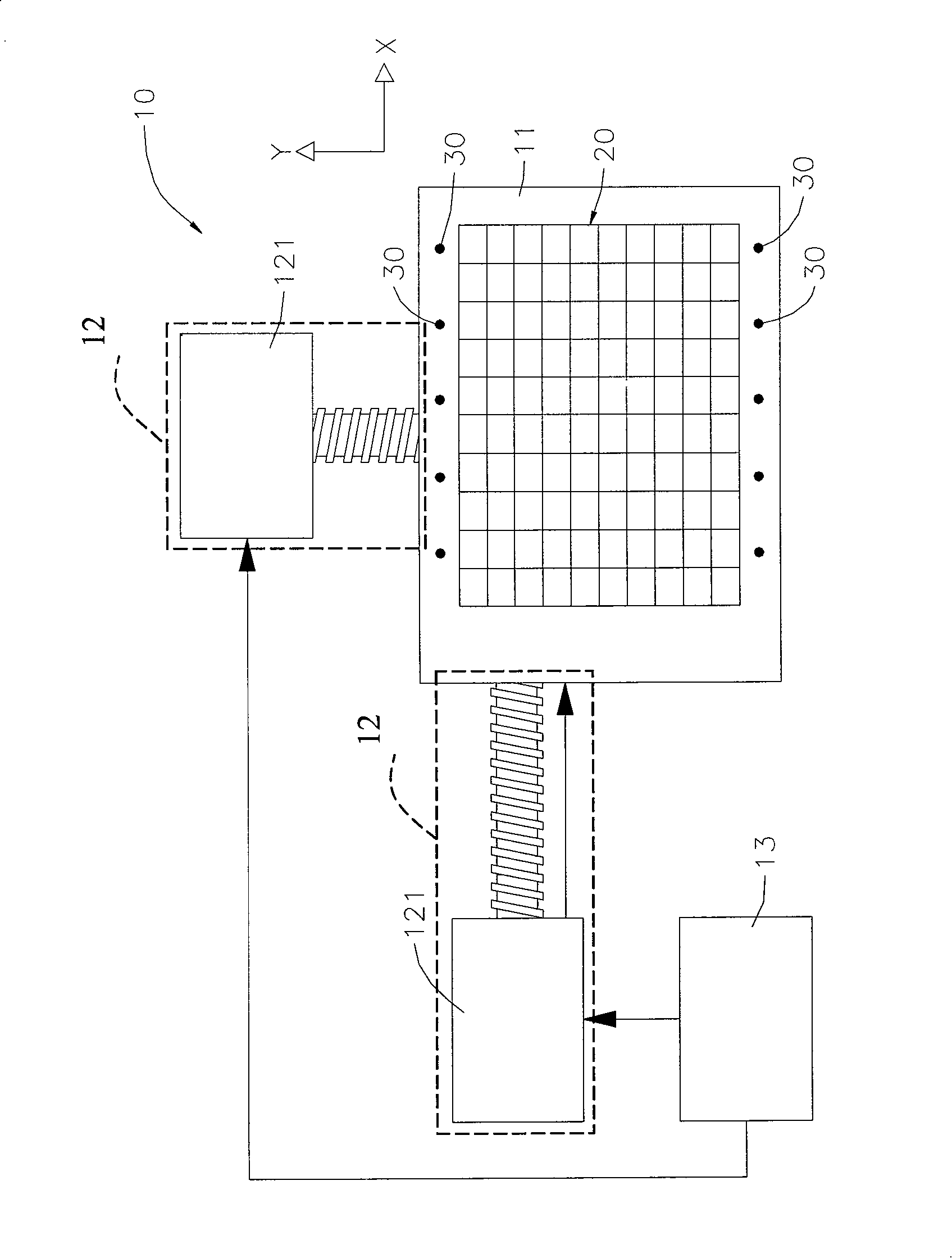
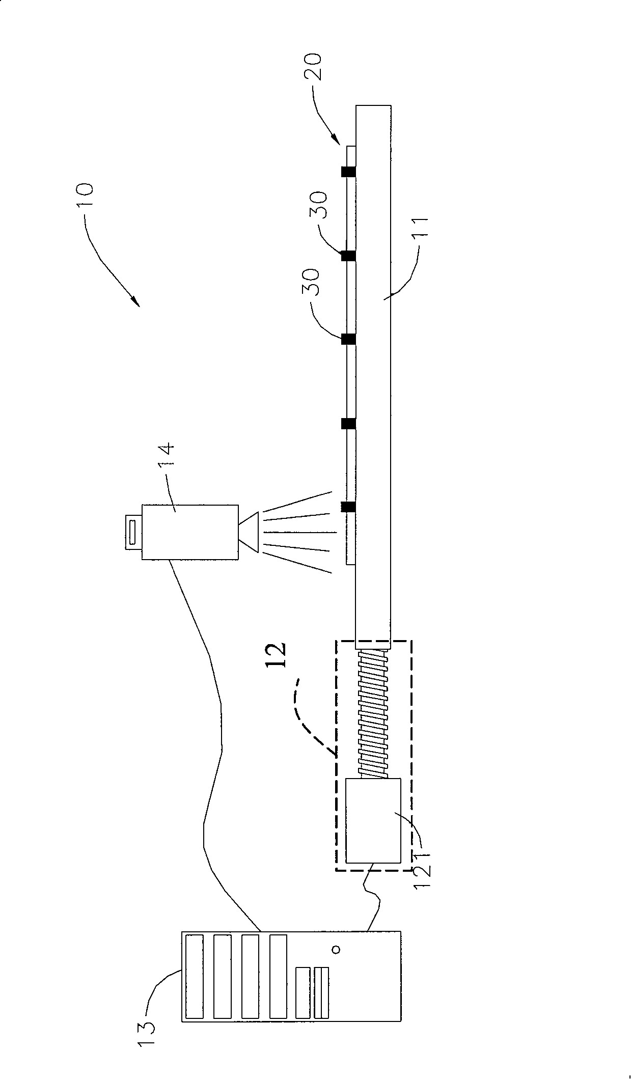
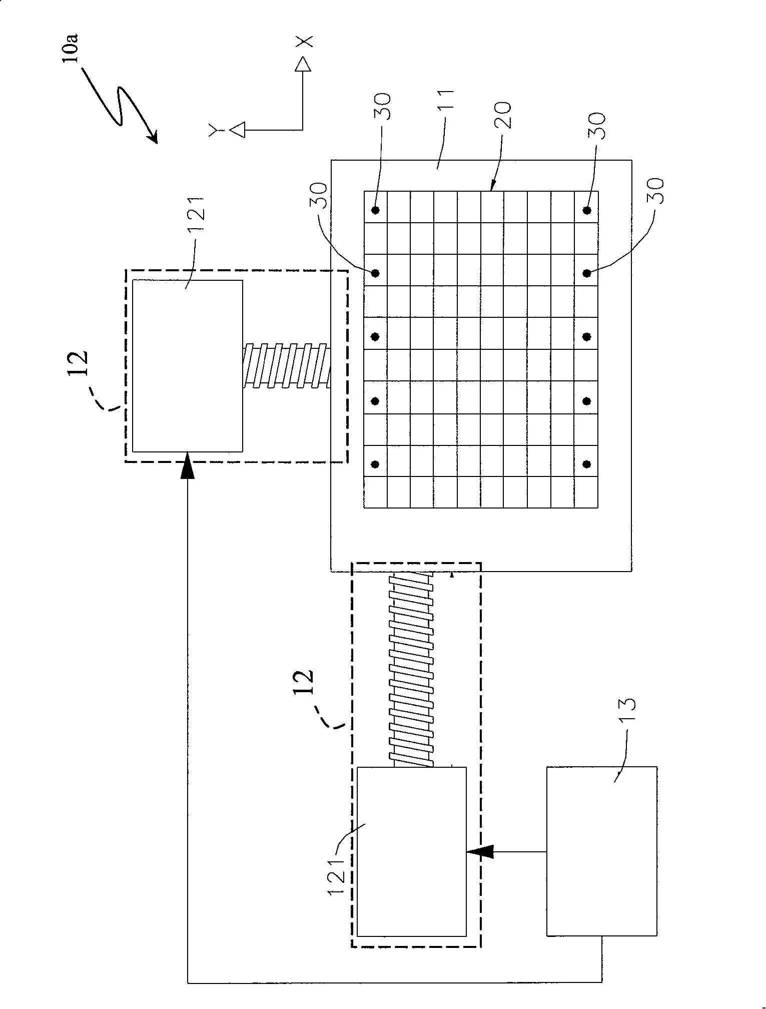
[0028] See first figure 1 and figure 2 Shown is the first preferred embodiment of the image detection device (10) of the present invention, which includes:

[0029] a test platform (11), on which the panel to be tested (20) is placed;

[0030] Plural positioning marks (30) are arranged on the test platform (11), and the straight lines (L) formed by two pairs of positioning marks (30) are used for judging the image overlap of adjacent areas, as shown in Figure 4A , and each positioning mark (30) is a reflective material or a luminescent material;

[0031] The two-axis driving device (12) is arranged on both sides of the test platform (11) to drive the test platform (11) to move horizontally in the X or Y direction, and the shaft driving device (12) can be a A linear motion device comprising a servo motor (121);

[0032] A control host (13), which has a built-in image processing program and a motor driver, and is electrically connected to the servo motor (121) to control t...


PUM


Abstract

The invention provides a method and a device with a high positioning and high accuracy image detection function applicable to planar display panel. A complex positioning marks and a to-be-detected panel are arranged on the detection platform of an image detection device. The straight line fabricated by positioning marks in groups of two superposes the to-be-detected panel. When complex image of the to-be-detected panel on the detection platform are obtained, the images then bear the positioning mark image, and thus the positioning marks in groups of two not only can be used as the separation line of the overlapped area in the neighboring images, but also can delete accurately the overlapped region of the neighboring images when the complete image of the to-be-detected panel is reformed. Therefore, problems of repeated analysis or being unable to detect are avoided when defect analysis is carried out later on.

Description

technical field [0001] The invention relates to a display detection device, especially an image detection device with high precision and high efficiency, which is applied to detect process defects of flat display panels. Background technique [0002] Since the structure formed in each process of semiconductor products is quite small (about a few hundred microns in terms of a single wire diameter), it is impossible to inspect its defects with human eyes, and it is necessary to confirm whether different process steps are correct during the process. There are defects, so the current panel manufacturers have built-in digital image detection devices, please refer to Figure 5 As shown, the digital image detection device (50) includes: [0003] A test platform (51) is for the panel to be tested (60) to be placed on it, wherein the panel to be tested is composed of a plurality of panel units; [0004] Two shaft driving devices (52) are arranged on the side of the test platform (51...

Claims


Application Information

Patent Timeline
Patent Type & Authority Applications(China)
IPC IPC(8): G09G3/00G01B11/00G01R31/00G01M11/00G02F1/13G01C11/00
Inventor 洪燕忠何昆璋王文宏林世明林林
Owner WINTEK CORP
Learn More