
Bearing unit for a long rotor blade of a wind power installation, wind power installation comprising one such rotor blade bearing arrangement, and method for operating one such wind power installation

A technology for rotor blades and wind power equipment, which is applied in the direction of wind power engines, rotating bearings, roller bearings, etc. in the same direction as the wind. It can solve the problems of increasing structural expenses, prevent sand and dust intrusion, and improve service life.

Inactive Publication Date: 2008-06-04
IMO HOLDING GMBH
View PDF1 Cites 21 Cited by
  • Summary
  • Abstract
  • Description
  • Claims
  • Application Information

AI Technical Summary

Problems solved by technology

But the use of two bearing units with a total of four bearing locations, all of which are designed for high stress, itself increases the structural outlay, in particular the need for a separate inner and outer ring for each bearing as a raceway

Method used


Image

  • Bearing unit for a long rotor blade of a wind power installation, wind power installation comprising one such rotor blade bearing arrangement, and method for operating one such wind power installation
  • Bearing unit for a long rotor blade of a wind power installation, wind power installation comprising one such rotor blade bearing arrangement, and method for operating one such wind power installation
  • Bearing unit for a long rotor blade of a wind power installation, wind power installation comprising one such rotor blade bearing arrangement, and method for operating one such wind power installation

Examples


Embodiment Construction

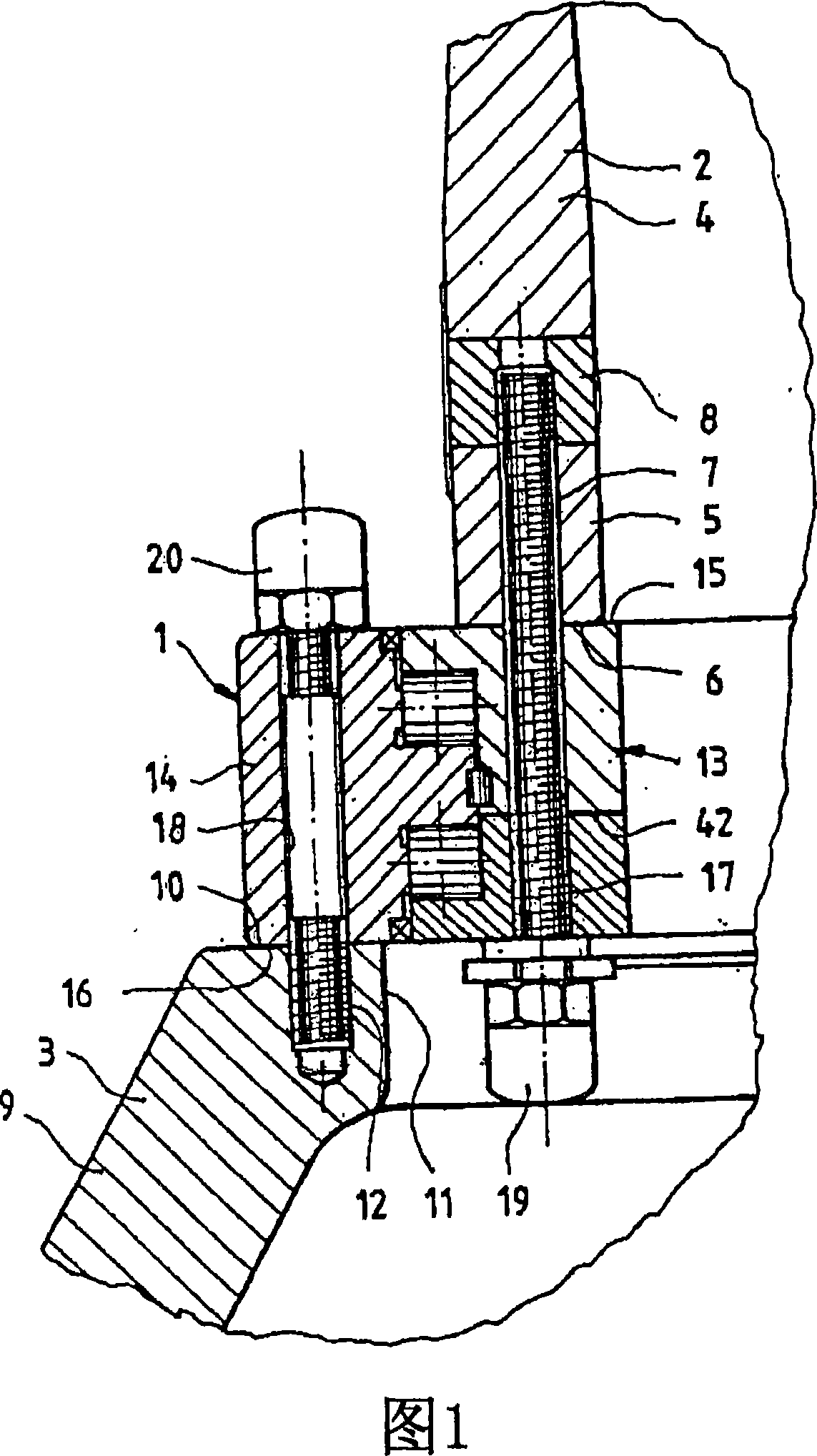
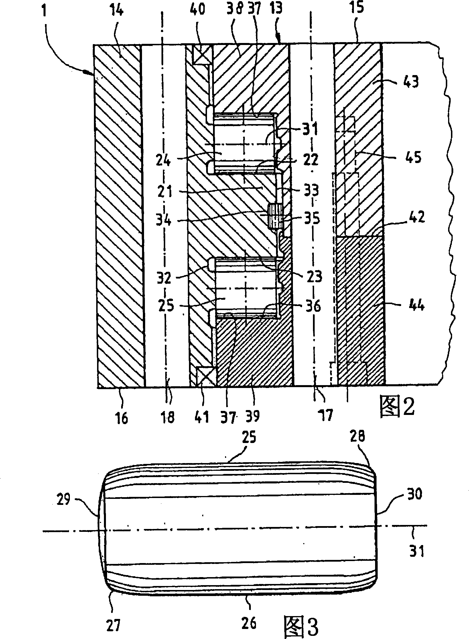
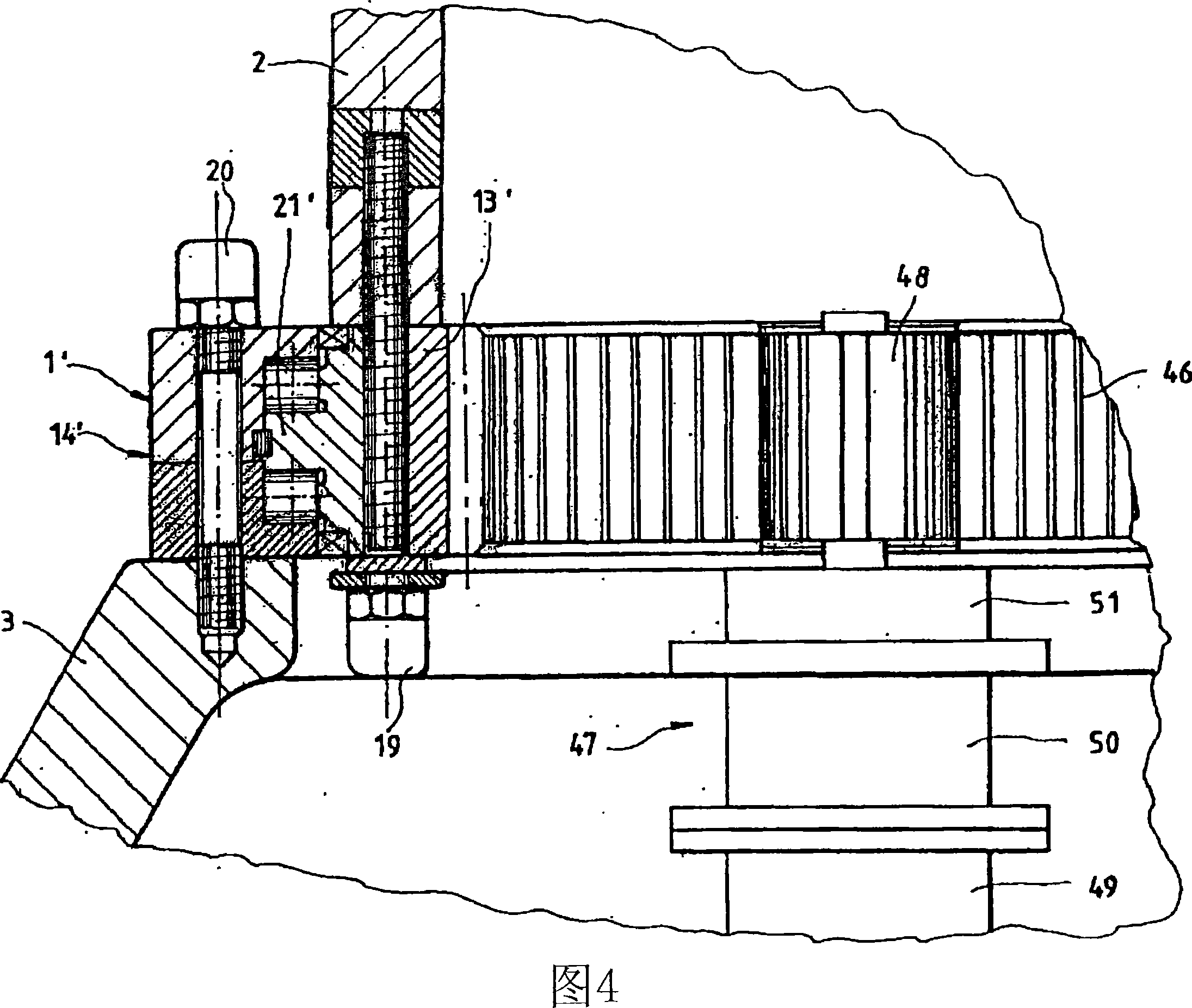
[0048] The blade bearing 1 according to the invention is used in wind power installations and there for the rotatable connection of a rotor blade 2 to a rotor hub 3 .

[0049] The rotor blade 2 usually consists of fiber composite material and is designed in the manner of an airfoil. To save weight, the rotor blade 2 is designed as a shell surface 4 surrounding the inner cavity, which merges at the rear end 5 of the rotor blade 2 into a cylindrical shell shape with a diameter of, for example, approximately 2 m-3 m. The planar rear connecting surface 6 therefore has a ring-shaped outer shape. Located on the connecting surface 6 are rim-shaped blind holes 7 , which each lead to an anchoring body 8 of hard material, for example iron, which is inserted into the rotor blade 2 . The blind hole 7 continues in the anchoring body 8 as an internally threaded hole.

[0050] The rotor hub 3 has a rigid bead 9 and a planar annular connection surface 10 for each rotor blade 2 , which runs ...


PUM


Abstract

The invention relates to a bearing unit for a long rotor blade, especially a wind power installation, said bearing unit comprising two annular elements that can be rotated in relation to each other and are directly or indirectly connected to the rotor blade hub and to the rotor blade, and at least two running tracks that can be axially staggered in relation to each other and comprise peripheral rolling bodies with an approximately cylindrical shape, i.e. each comprising a lateral surface that is rotationally symmetrical to a rotational axis in a very precise manner. The aim of the invention is to be able to fully absorb the tipping moment caused by the wind pressure on the rotor blade and on the bearing unit, and optionally to absorb other forces and other moments. To this end, two running tracks are arranged between the two connection elements, are axially staggered in relation to each other, and comprise rolling bodies with an approximately cylindrical shape, said rolling bodies being oriented in such a way that the rotational axes thereof intersect the longitudinal axis of the rotor blade in question at an angle of between 30° and 90°. The invention also rates to a wind power installation provided with one such rotor blade bearing arrangement, and to a method for operating one such wind power installation. The at least one rotor blade in question is continuously rotted about the longitudinal axis thereof during the option of the wind power installation.

Description

technical field [0001] The invention relates to a bearing unit, in particular to a longitudinally extending rotor blade of a wind power plant, comprising at least two axially offset raceways and rolling elements running around them; in addition to a wind power plant equipped with such a rotor blade bearing structure. A device and a method for operating such a wind power device. Background technique [0002] Wind power installations—and therefore in particular their rotor diameters—are becoming larger and larger. Correspondingly, the requirements for all supports and bearing units are also increasing. This also applies to the blade bearings, which are used to adjust the angle of attack of the blades and can be adapted to different wind speeds, on the one hand for optimal power regulation and on the other hand in the form of blackouts in high winds. In this case, the largest load is the overturning moment, which directs the wind load concentrated at the center of pressure CP...

Claims


Application Information

Patent Timeline
Patent Type & Authority Applications(China)
IPC IPC(8): F03D11/00F03D1/06F03D7/02
CPCF03D1/0658F05B2260/71Y02E10/723F16C19/381F16C2360/31F05B2270/304F05B2240/52F03D11/0008F03D7/0224F05B2240/54F05B2260/4031F16C33/34F05B2250/314F16C2300/14Y02E10/722F05B2250/313F16C35/06Y02E10/721F05B2270/109F16C19/38F03D80/70Y02E10/72
Inventor 埃里希·鲁斯维尔纳·施罗佩尔
Owner IMO HOLDING GMBH
Learn More