
Bio-electrical impedance measuring method and apparatus

A technology of bioelectrical impedance and measurement methods, applied in diagnostic recording/measurement, medical science, sensors, etc., can solve problems such as complex design schemes, interference, errors, etc., to reduce circuit costs, reduce contact impedance, and avoid hardware errors Effect

Inactive Publication Date: 2008-06-11
CHONG QING BORN FUKE MEDICAL EQUIP CO LTD
View PDF0 Cites 33 Cited by
  • Summary
  • Abstract
  • Description
  • Claims
  • Application Information

AI Technical Summary

Problems solved by technology

Biological tissue multi-frequency impedance measurement instrument is not yet practical
In addition, the existing instruments in the development and experiment stage are relatively complex in design, simple in performance, simple in algorithm and realized in function, high in cost, and do not have the function of extraction and analysis of impedance model parameters, and cannot monitor biological impedance in vivo for a long time Model parameters, etc.
[0006] In addition, the hardware part used in the measurement will produce errors and interference during the measurement process, such as: the surface potential signal error caused by the contact resistance caused by the electrode paste, the interference signal generated by various instruments, etc., will cause the electrical impedance calculation. The purity of the electrical signal used is not enough, that is, it cannot accurately reflect the impedance distribution of the area to be measured, resulting in unsatisfactory imaging accuracy, and cannot accurately and truly reflect the changes in the body's condition

Method used

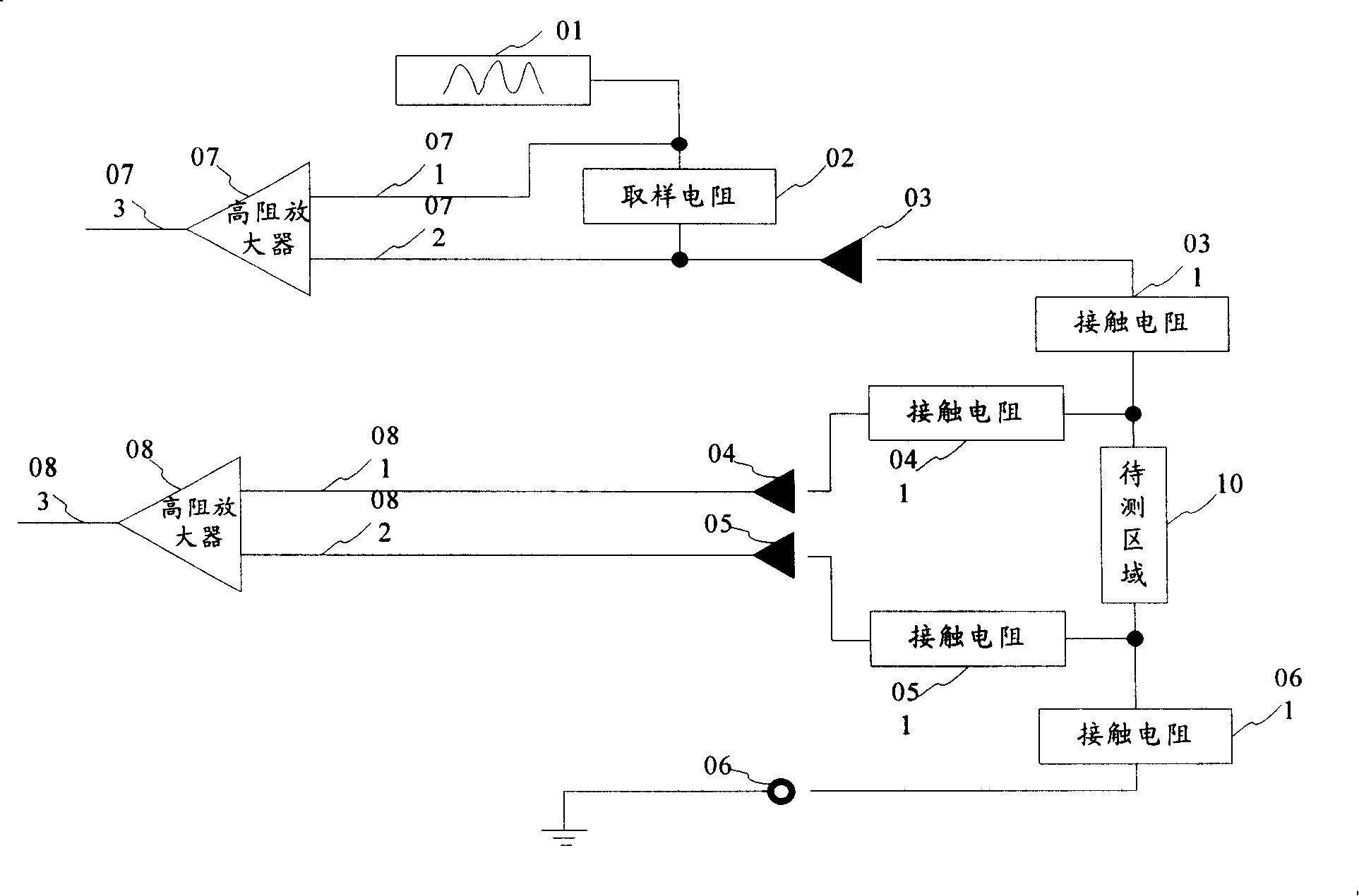
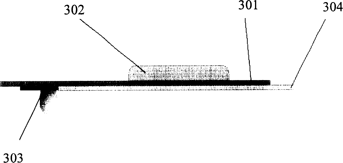

Image

  • Bio-electrical impedance measuring method and apparatus
  • Bio-electrical impedance measuring method and apparatus
  • Bio-electrical impedance measuring method and apparatus

Examples


Embodiment Construction

[0063] In order to make the above objects, features and advantages of the present invention more comprehensible, the present invention will be further described in detail below in conjunction with the accompanying drawings and specific embodiments.

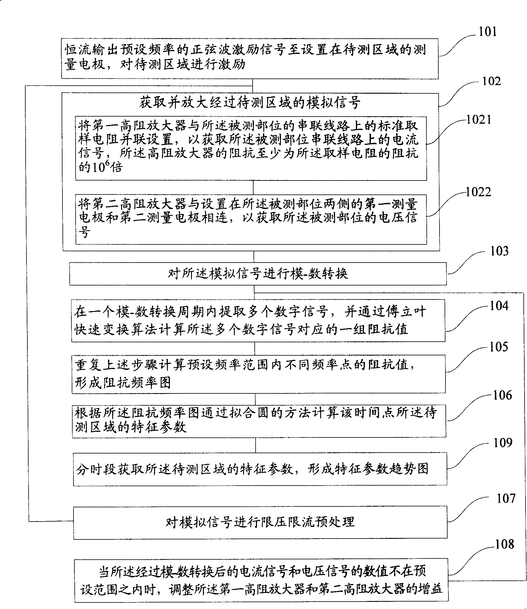
[0064] refer to figure 1 , is a flow chart of a method for measuring bioelectrical impedance of the present invention, comprising the following steps:

[0065] Step 101: Constant current outputting a sine wave excitation signal with a preset frequency to the measuring electrodes set in the area to be measured to excite the area to be measured;

[0066] Step 102: Acquiring and amplifying the analog signal passing through the area to be tested;

[0067] Step 103: Perform analog-to-digital conversion on the analog signal;

[0068] Step 104: Extract multiple digital signals within one analog-to-digital conversion cycle, and calculate a set of impedance values ​​corresponding to the multiple digital signals through a Fast Fourier Tra...


PUM

PropertyMeasurementUnit
Diameteraaaaaaaaaa

Abstract

The invention discloses a measuring method of biological electric impedance, which is characterized in that the method comprises constant-current outputting the sine wave pumping signal with preset frequency to the measuring electrode which is arranged in a region for measuring, inspiring the region for measuring, receiving and magnifying the analog signal which passes through the region for measuring, A / D converting the analog signal, extracting a plurality of digital signals in one cycle of A / D conversion, calculating a group of impedance values corresponding to a plurality of digital signals through the fast Fourier algorithm, calculating the impedance values of different frequency points in the range of preset frequency through repeating above steps to form an impedance frequency diagram, and calculating the characteristic parameter of the region for measuring at the time point through coincidence circularity method according to the impedance frequency diagram. The invention provides pure electrical signal through effectively shielding inference signal, thereby guaranteeing the measurement precision. The invention adopts the fast Fourier algorithm and coincidence circularity method, which improves the precision of impedance calculation and effectively reduces the cost of circuit.

Description

technical field [0001] The invention relates to the field of bioelectrical impedance detection, in particular to a method and device for measuring bioelectrical impedance. Background technique [0002] Bioelectrical impedance measurement is a detection technology that uses the electrical characteristics of biological tissues and organs and their changes to extract biomedical information related to physiological and pathological conditions. The bioelectrical impedance measurement method can be used to extract Corresponding electrical characteristics and their variation information. It can be used to measure and monitor various electrical parameters of organisms, such as electrocardiography, bioimpedance measurement, electroencephalography, etc., including placing electrodes on the organism, and then measuring during or after electrical stimulation electric signal. [0003] For organisms, due to the similarities and differences in cell types, arrangement density, intercellul...

Claims


Application Information

Patent Timeline
IPC IPC(8): A61B5/053
Inventor 熊新翔蒋辉吴琪何为王平
Owner CHONG QING BORN FUKE MEDICAL EQUIP CO LTD
Learn More