Non-needle positive pressure enclosed transfusion joint valve

A joint valve, liquid technology, applied in the directions of valves, hypodermic injection devices, and devices introduced into the body, etc., can solve the problems of cumbersome operation, troublesome operation, and needle stick injuries for medical staff, so as to facilitate clinical fixation and portability, and save materials. The effect of small cost and external size

Inactive Publication Date: 2008-06-11
张亚平
View PDF5 Cites 27 Cited by
  • Summary
  • Abstract
  • Description
  • Claims
  • Application Information

AI Technical Summary

Problems solved by technology

However, there are certain defects and deficiencies in the above-mentioned technology: before each use, the rubber sealing cap to be punctured on the heparin cap must be partially sterilized, and the rubber plug of the heparin cap must be punctured with an injection needle to be connected with the infusion tube so that the medicinal liquid can pass through The puncture needle tube enters the infusion tube, which is troublesome to operate and has the risk of being stabbed by the needle; in clinical practice, the patient cannot use anticoagulants such as heparin due to certain diseases (such as hemophilia, or blood coagulation disorder). The sealing method of the heparin cap on the infu...

Method used


Image

  • Non-needle positive pressure enclosed transfusion joint valve
  • Non-needle positive pressure enclosed transfusion joint valve
  • Non-needle positive pressure enclosed transfusion joint valve

Examples


specific Embodiment 2

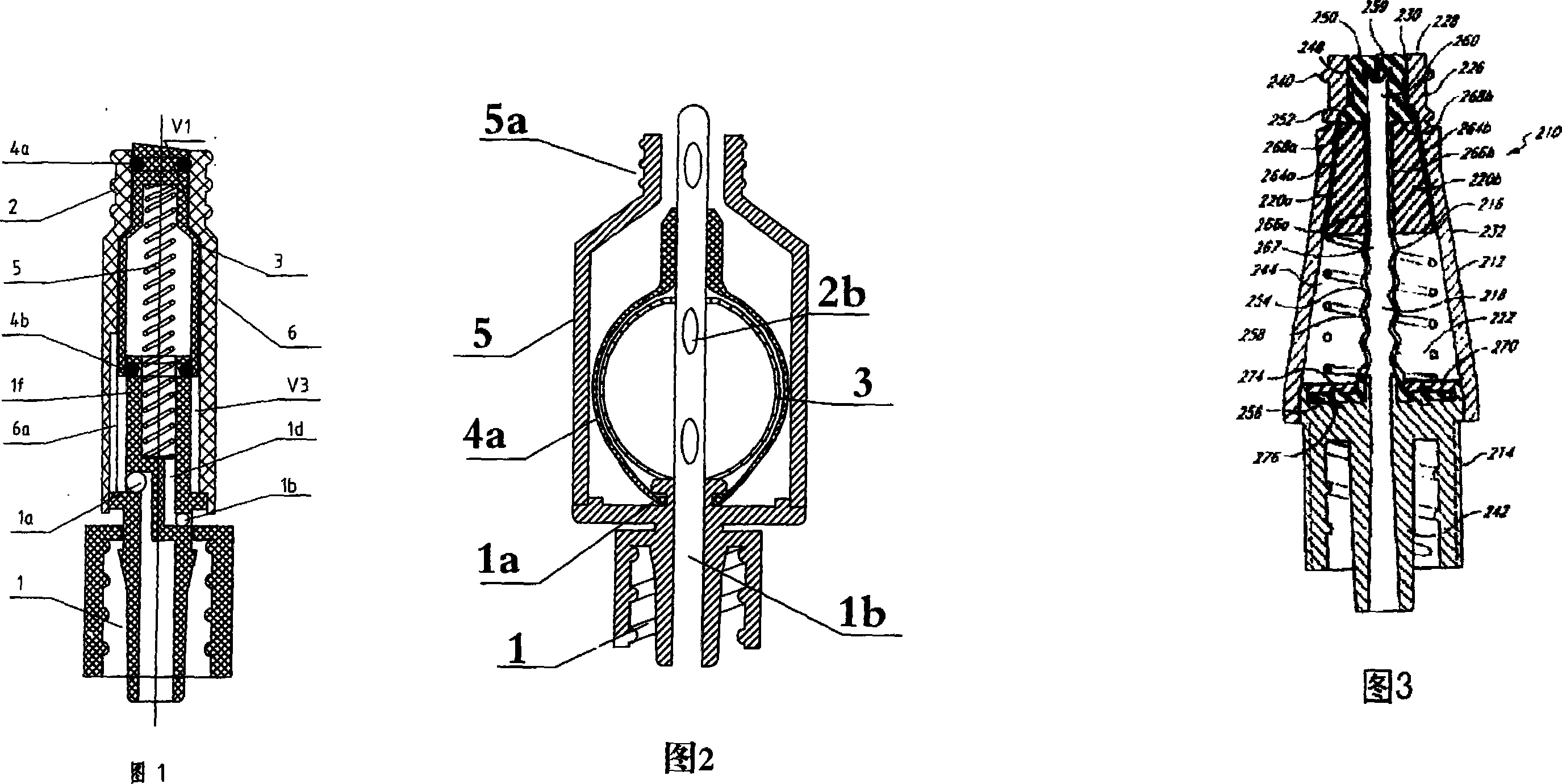
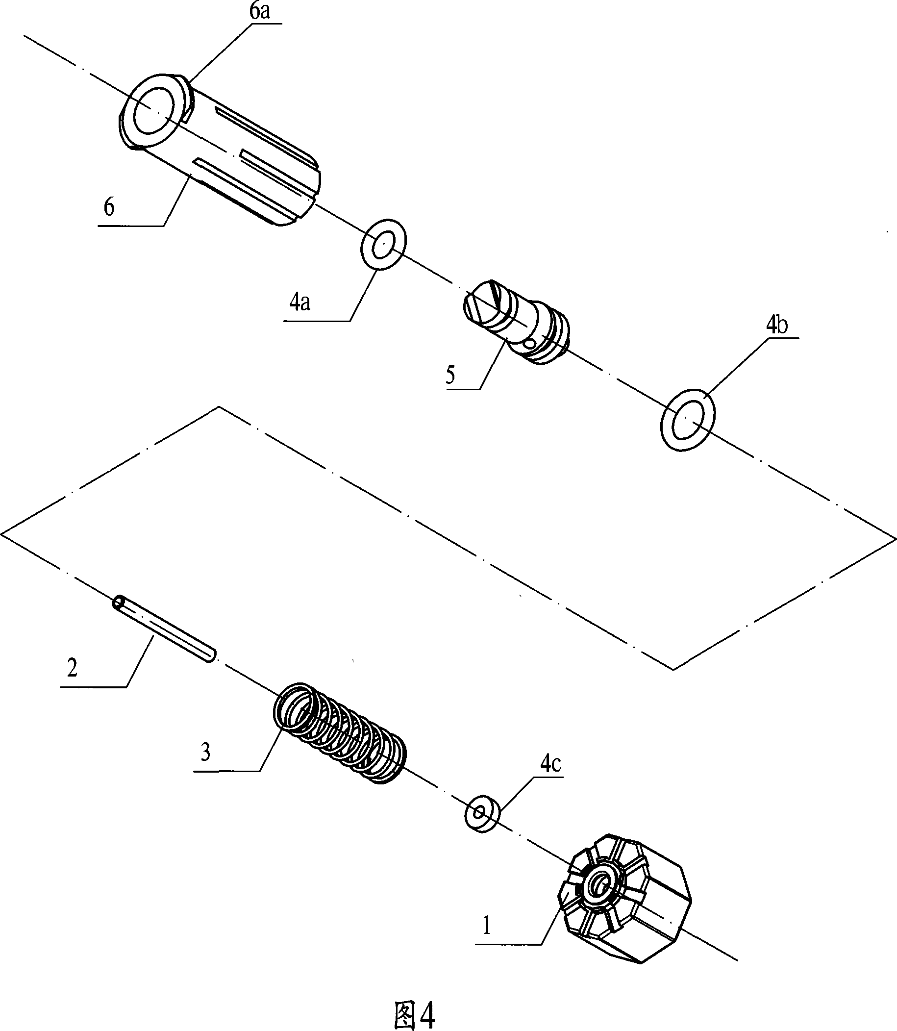
[0031] It can be seen from FIG. 7 that the needleless positive pressure airtight infusion joint valve of the present invention is mainly composed of a housing 6, a piston 5, sealing rings 4a, 4b, 4c, a spring 3, a liquid connecting pipe 2, and a base 1.

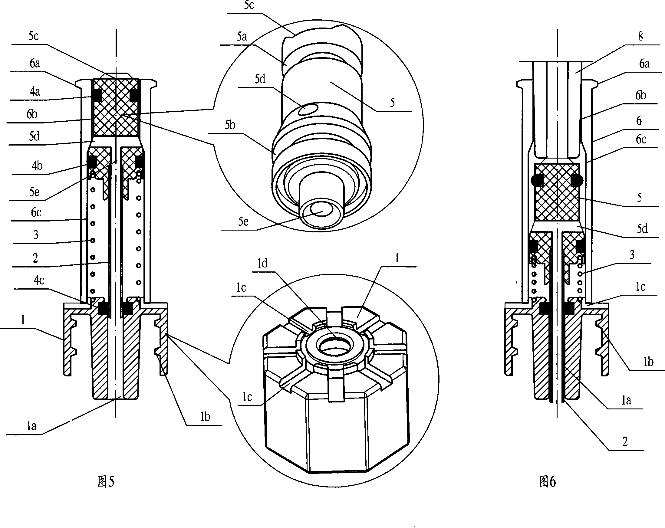
[0032] It can be seen from Fig. 8 that the base 1 and the housing 6 constitute the shell of the needle-free airtight infusion joint valve of the present invention, the outer side of the upper end of the housing 6 is threaded to form a screw socket 6a of the Luer structure, and the inner diameter 6c of the lower section of the housing 6 is the inner diameter of the upper section 1.1 times more than 6b, there is a piston 5 in the housing 6 whose outer diameter is compatible with the inner diameter of the housing 6 but can slide up and down. There is a sealing ring 4a, the diameter of the lower section of the piston 5 is more than 1.1 times that of the upper section, the outer edge of the lower end of the piston 5 has an annular ...

specific Embodiment 3

[0034] It can be seen from Fig. 10 that the needleless positive pressure airtight infusion joint valve of the present invention is mainly composed of a housing 6, a piston 5, sealing rings 4a, 4b, a spring 3, a liquid connecting pipe 2A, and a base 1.

[0035] It can be seen from Fig. 11 that the base 1 and the housing 6 constitute the shell of the needle-free airtight infusion joint valve of the present invention, the outer side of the upper end of the housing 6 is threaded to form a screw socket 6a of the Luer structure, and the inner diameter 6c of the lower section of the housing 6 is the inner diameter of the upper section 1.1 times more than 6b, there is a piston 5 in the housing 6 whose outer diameter is compatible with the inner diameter of the housing 6 but can slide up and down. There is a sealing ring 4a, the diameter of the lower section of the piston 5 is more than 1.1 times that of the upper section, the outer edge of the lower end of the piston 5 has an annular g...

specific Embodiment 4

[0037]It can be seen from FIG. 13 that the needleless positive pressure airtight infusion joint valve of the present invention is mainly composed of a housing 6, a piston 5, sealing rings 4a, 4b, a spring 3, a liquid connection hose 2B, and a base 1.

[0038] It can be seen from Fig. 14 that the base 1 and the housing 6 constitute the shell of the needle-free airtight infusion joint valve of the present invention, the upper end of the housing 6 is threaded on the outer side to form the screw socket 6a of the Luer structure, and the inner diameter 6c of the lower section of the housing 6 is the inner diameter of the upper section 1.1 times more than 6b, there is a piston 5 in the housing 6 whose outer diameter is compatible with the inner diameter of the housing 6 but can slide up and down. There is a sealing ring 4a, the diameter of the lower section of the piston 5 is more than 1.1 times that of the upper section, the outer edge of the lower end of the piston 5 has an annular ...


PUM


Abstract

The invention relates to a needle-free barotropic airtight transfusion joint valve, wherein an outer casing is constituted by a casing body and a chassis, a piston which can move from top to bottom is arranged in the casing body, sealing rings are respectively embedded in annular grooves which are arranged on the upper and lower ends of the piston, the diameter of the lower section of the piston is larger than that of the upper section of the piston, a hole is arranged between the upper section and the lower section of the piston and is communicated with a central hole which is arranged on the lower section of the piston, a liquid connecting tube which is fixed in the central hole is inserted into a drain tube on the chassis and movably sealed by the sealing ring, a fluid channel is constituted by a jack on the upper section of the casing body, a groove on the upper end of the piston, a lateral hole of the piston, the central hole on the lower section of the piston, the fluid connecting tube and the drain tube, an air compensating channel is constituted by eight grooves which are arranged on the upper end surface of the chassis and the casing body, and a liquid positive pressure cavity is constituted by the piston which is penetrated through the sealing ring and the casing body.

Description

technical field [0001] The invention relates to a joint valve for liquid infusion, in particular to a needle-free positive pressure airtight transfusion joint valve which can generate positive pressure and prevent venous blood backflow for medical purposes. Background technique [0002] At present, in the process of intravenous infusion treatment, due to the limitations of the disease or the patient's own conditions, long-term repeated infusion treatment is often required, or the drug solution needs to be temporarily injected into the infusion pipeline several times during the infusion process, and enters the blood vessels of the human body to achieve The purpose of treating diseases; in order to reduce the damage to the patient's superficial venous vessels, as well as to alleviate the pain of the patient and the labor intensity of the medical staff, in this case, the structure of the three-way tube and the heparin cap is mostly connected in series in the pipeline of the intr...

Claims


Application Information

Patent Timeline
IPC IPC(8): A61M39/22A61M5/00A61M5/14
Inventor 张亚平张亚根
Owner 张亚平
Why Eureka
Try Eureka