Eureka AIR delivers breakthrough ideas for toughest innovation challenges, trusted by R&D personnel around the world.

Ore slurry rotational flow floatation method rotational flow flotation column and flotation unit used thereof

A flotation column and pulp technology, which is applied in the field of swirl flotation column and flotation device, swirl flotation, and mineral flotation, can solve the problem of unacceptable mineral processing manufacturers, small investment, difficulty in finding reasons, and accountability, etc. question

Inactive Publication Date: 2008-06-11
李宾
View PDF1 Cites 12 Cited by
  • Summary
  • Abstract
  • Description
  • Claims
  • Application Information

AI Technical Summary

Problems solved by technology

Because flotation pulp is different from sewage treatment, it changes greatly and needs to be adjusted at any time. Therefore, manual control of process parameters like the existing technology often leads to product quality degradation or scrapping due to out-of-control and other reasons, resulting in huge economic losses.
It is also very difficult to find out the reason and find out the responsibility afterwards.
The automatic control system in the existing technology requires too much investment in transformation, which cannot be accepted by many mineral processing manufacturers.
How to make the monitoring and control effect good, and make its investment less, which is accepted by mineral processing enterprises, is also a technical problem that has not been solved in the prior art.

Method used


Image

  • Ore slurry rotational flow floatation method rotational flow flotation column and flotation unit used thereof
  • Ore slurry rotational flow floatation method rotational flow flotation column and flotation unit used thereof
  • Ore slurry rotational flow floatation method rotational flow flotation column and flotation unit used thereof

Examples


Embodiment 1

[0150] Through the industrial test of lead-zinc ore lead / zinc-sulfur, lead is extracted from the pulp by cyclone flotation. Through the test, it is found that the best condition of regulating potential flotation separation and regulating frequency conversion feeding pressure is: the pressure of feeding pulp is: 3.00 kg / cm 2 ; The volume of air inhaled by the swirl jet suction foamer (negative pressure) is 0.35 meters 3 / min; the baffle plate of the flotation tank (directly opposite to the ore nozzle) is adjusted to 60% of the front and rear distance to control the micro-bubble effect of the pulp; the average diameter of the pulp foam is 0.60 cm; the pulp foam layer is 30 cm; the pH of the pulp is 12.45, The pulp potential is 170mV, diethylsulfide nitrogen (DDTC) is used as the main collector for lead selection, lime is used as the adjustment and stabilizer of pH and pulp potential, the concentration, flow and grade of the pulp are monitored, and the concentration and flow of ...

Embodiment 2

[0152] Adjust the valve to control the amount of air inhaled by the swirl injector (negative pressure) and the baffle of the flotation tank (directly opposite to the ore feeding nozzle) to adjust the front and rear distances, and adjust the slurry potential and pH value. With the increase of lime consumption, the pH of the slurry increases , the slurry potential decreases, and at the same time the ore grade and lead recovery rate of the lead coarse concentrate gradually increase, when the pressure of the ore slurry is: 3.50 kg / cm 2 ;Valve control swirl injector (negative pressure) suction air volume is 0.40 meters 3 / min; the baffle plate of the flotation tank (directly opposite to the ore nozzle) is adjusted to 50% of the front and rear distance to control the microbubble of the pulp; the average diameter of the pulp foam is 0.50 cm; when the thickness of the foam layer is greater than 35 cm; the pH of the pulp is 12.3 --12.6 within a narrow range, the slurry potential is al...

Embodiment 3

[0154] Tests have proved that the conditions for the optimum foam average diameter and the thickness of the foam layer in the flotation tank for lead / zinc-sulfur regulation and control of flotation separation are: the average diameter of the pulp foam is 0.30 cm; the thickness of the foam layer is greater than 40 cm; The pressure is: 3.00 kg / cm 2 ;The amount of air inhaled by the swirl jet (negative pressure) is 0.45 meters 3 / min; the baffle plate of the flotation cell (directly opposite to the ore nozzle) is adjusted to 50% of the front and rear distance to control the microbubble of the pulp; the pH of the pulp is 12.4, the potential of the pulp is 165mV, and DDTC is used as the main trap for lead selection Receiver. If other parameters are changed, the size of the foam diameter and the thickness of the foam layer of the flotation cell will change accordingly, which will directly affect the recovery rate of ore dressing. When the pressure of the ore feeding slurry is: 2.5...


PUM

PropertyMeasurementUnit
Heightaaaaaaaaaa

Abstract

The invention provides a cyclone floating method for slurry. In a mineral process of cyclone floatation, the equal diameter of slurry foams is controlled to be 0.10 centimeters-3.00 centimeters, and the thickness of a foam layer of the slurry is controlled to 3cm-50cm. The method for controlling the equal diameters of the slurry foams and the thickness of the foam layer of the slurry comprises adjusting a distance between a baffle plate and a slurry inlet which is in a floating slot, and adjusting air input quantity through adjusting a valve which is arranged on an air pipe of a foamier. A plurality of procedural parameters are monitored in real time during the mineral process. A cyclone spraying floating prop and a floating device which contains the cyclone spraying floating prop are additionally provided by the invention, and the cyclone spraying floating prop and the floating device are suitable to realize the method of the invention above. The separating operational cost of various minerals can be lowered by the invention, and manufacturing cost and the producing operational cost of a floatation machine can also be lowered greatly. The invention saves energy further, and compared with a common floatation machine, the invention can save energy 65%, compared with a traditional floating prop, the invention saves 45%, and the invention is applied to the separating fields of the various minerals.

Description

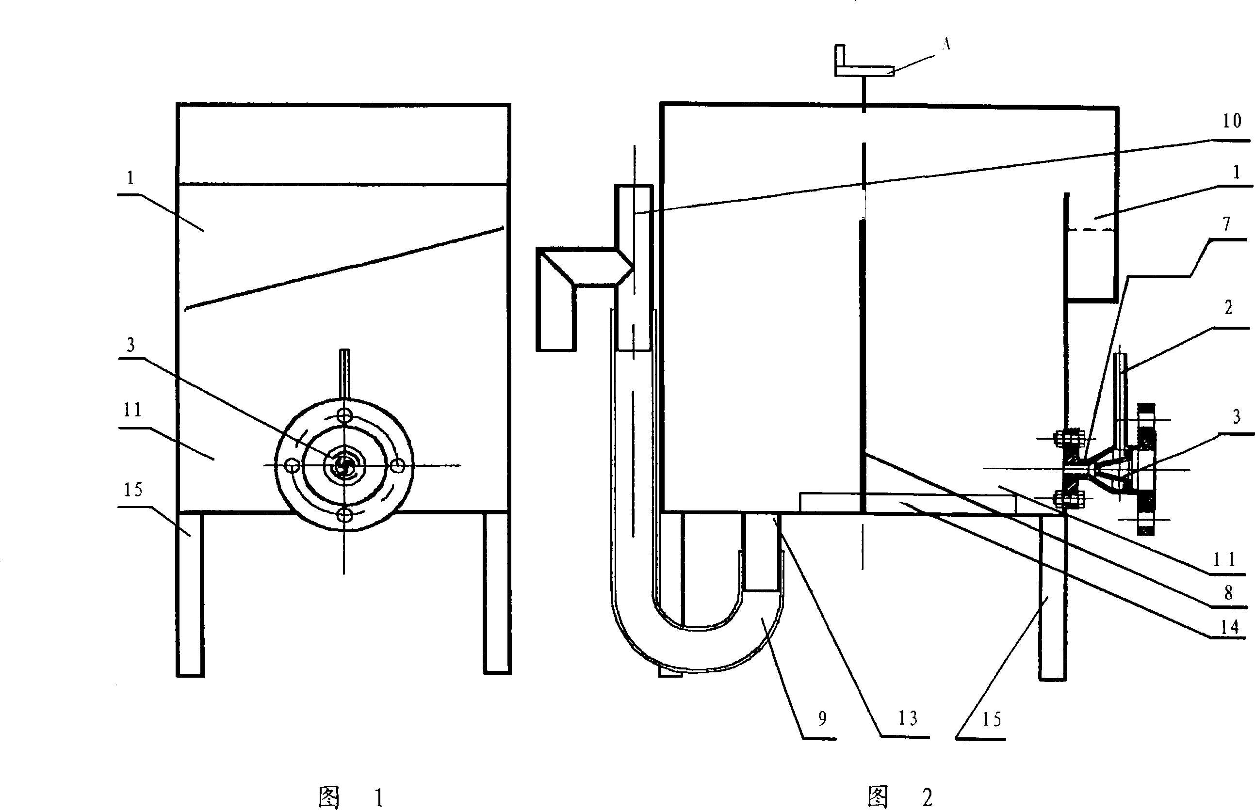
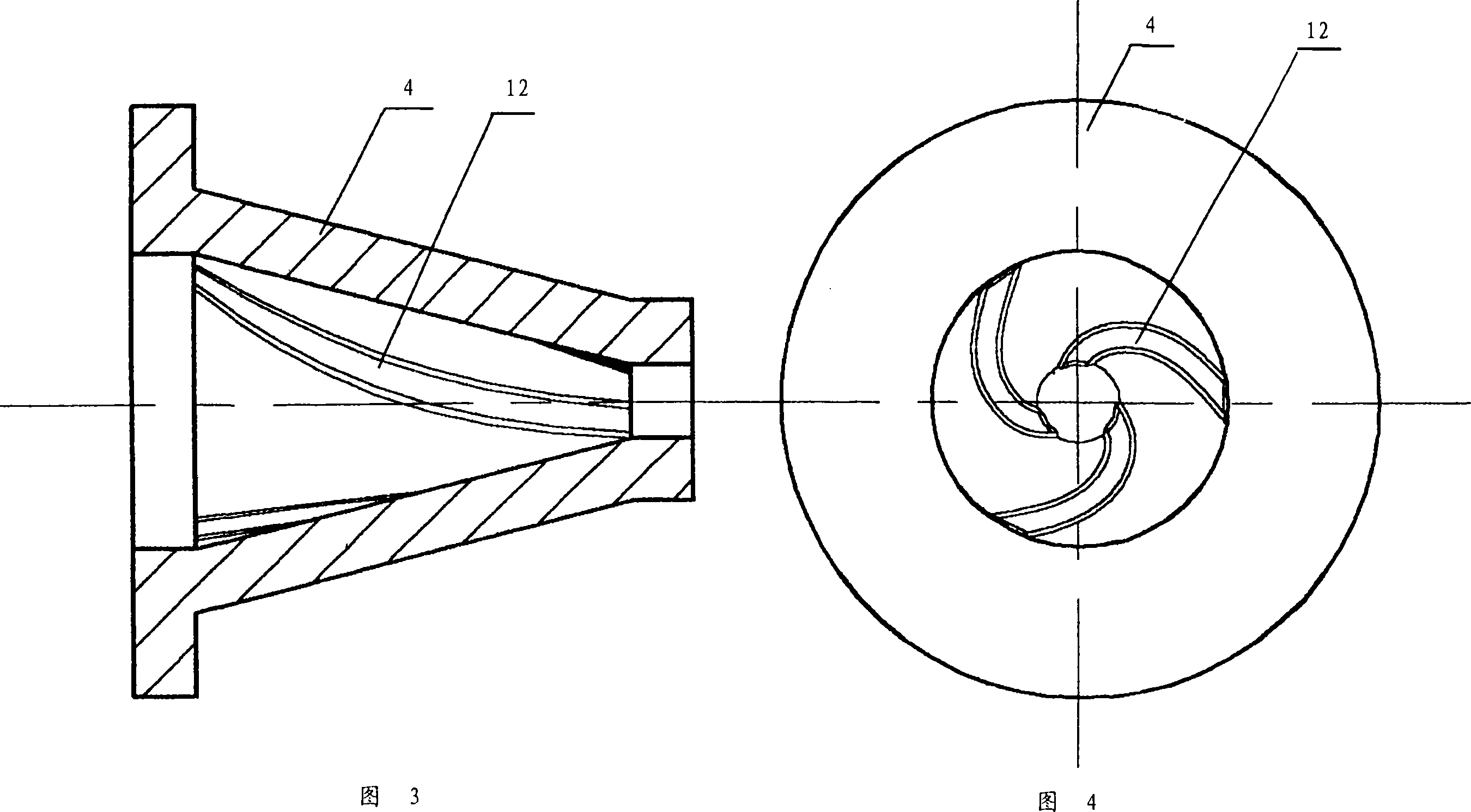
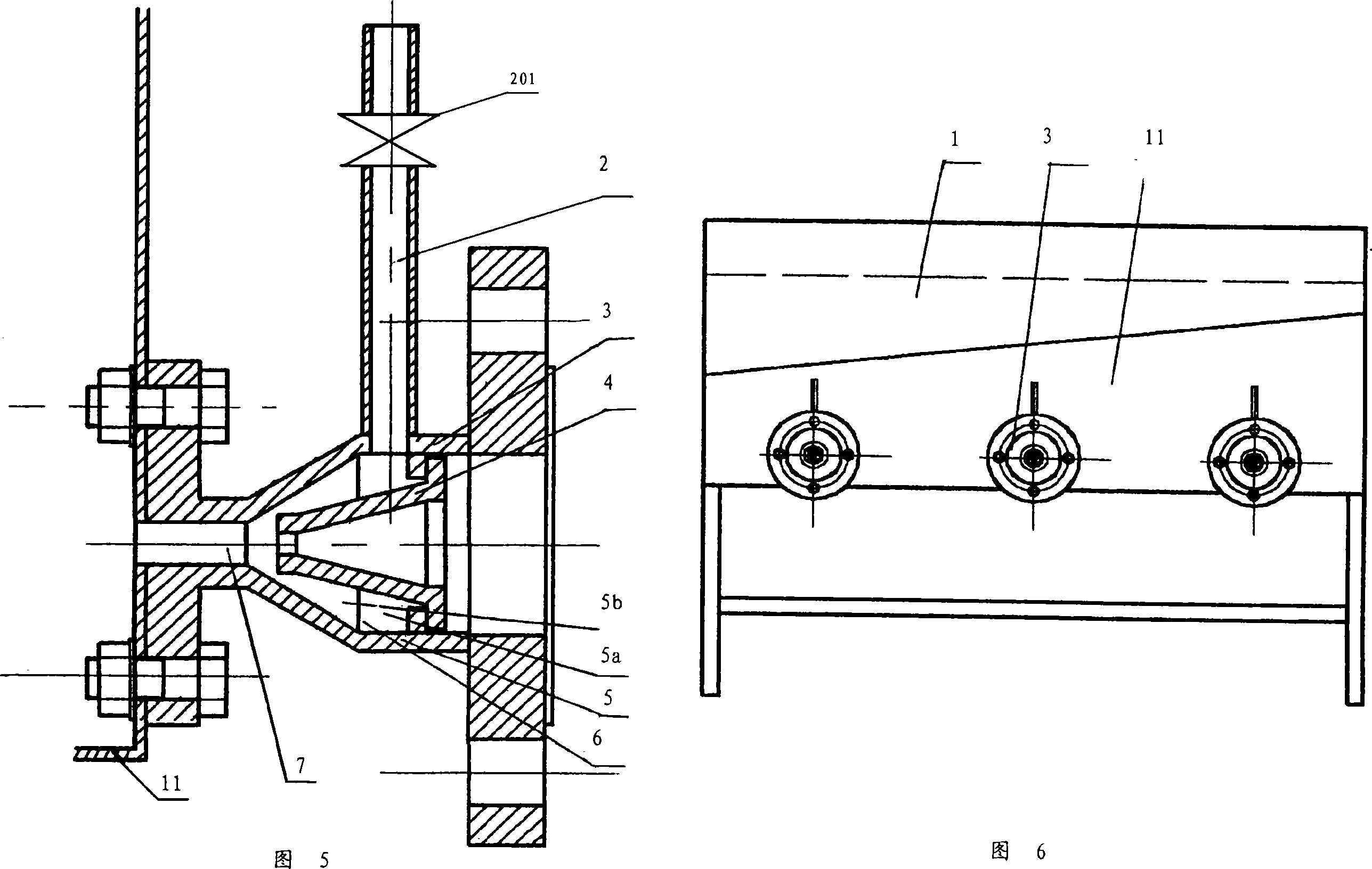
technical field [0001] The invention belongs to the technical field of mineral flotation, and relates to a mineral flotation method, in particular to a swirling flow flotation method. The invention also relates to cyclone flotation columns and flotation devices used in the method. Background technique [0002] Swirl flotation technology is a new flotation technology that has just been developed. With the birth of swirl jet flotation machine (patent number: 02252728.1), swirl flotation technology has been widely used in practical flotation applications. This swirl jet flotation machine has a swirl jet suction foamer with spiral deflectors and narrowing nozzles. Compared with other flotation machines, its advantages are: (1) large air volume, small bubbles, and air High capacity. The gas capacity ratio of ordinary conventional flotation machines is 15-25%, and the gas capacity ratio of swirl jet flotation machines is as high as 35-40%. (2) The energy consumption is low, whic...

Claims


Application Information

Patent Timeline
IPC IPC(8): B03D1/02B03D1/14B03B13/00
Inventor 李宾
Owner 李宾
Why Eureka
Eureka Blog
Learn More