Shipping pipe, manufacture method thereof and shipping having the same
A manufacturing method and technology for ships are applied in the field of conduits for ships and their manufacture and the field of ships with conduits for ships, which can solve the problems of long waiting time for processing, increased transportation costs, high manufacturing costs, etc. Cost reduction, the effect of realizing the manufacturing cost
- Summary
- Abstract
- Description
- Claims
- Application Information
AI Technical Summary
Problems solved by technology
Method used
Image
Examples
Embodiment approach 1
[0094] [Embodiment 1: Ship with conduit for ships]
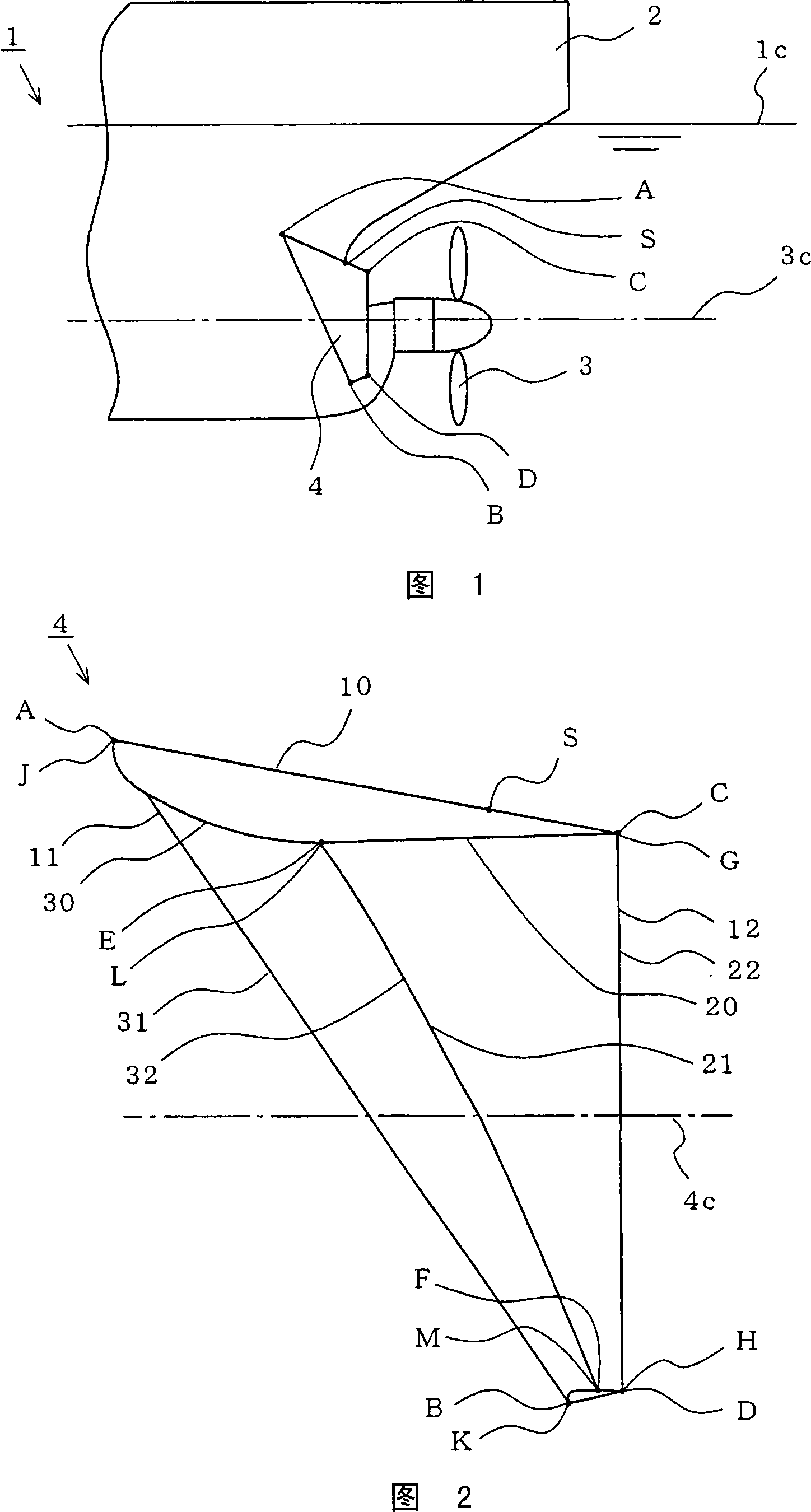
[0095] Fig. 1 is a partial side view showing an outline of a ship with a ship duct according to Embodiment 1 of the present invention. In FIG. 1 , a ship 1 with a ship duct has a hull 2 , a propeller 3 protruding from the stern of the hull 2 (on the right side in the figure), and a ship duct 4 provided on the stern of the hull 2 .
[0096] The conduit 4 for ships is arranged on both sides of the hull 2, and is roughly trapezoidal (in the figure, the line segment connecting position A-position B-position D-position C) in a side view (the same direction as the observation ship side) respectively. Formed), in the front view (the same direction as the observation of the stern) is a roughly semicircle (not shown). In addition, the ship duct 4 provided on the starboard side and the ship duct 4 provided on the port side are plane-symmetrical to each other, in the range near the bridge (upper side in the figure) and in the ra...
Embodiment approach 2
[0103] [Embodiment 2: Catheter for ships - one]
[0104] FIG. 2 is a side view showing the outline of a ship duct according to Embodiment 2 of the present invention. In FIG. 2 , the ship duct 4 is a ship installed on the starboard side of the ship 1 with the ship duct shown in FIG. 1 . Use a catheter.
[0105] The ship duct 4 has a duct outer plate 10 as a part of a cone whose diameter is larger on the bow side than on the stern side, and whose upper side (corresponding to the bridge side or water surface side) is longer than the lower side (corresponding to the ship bottom side or sea bottom side). Inside the duct outer panel 10 , the cylindrical stern side inner panel 20 whose upper side is longer than the lower side, and the bow side inner panel 30 housed in the duct outer panel 10 .
[0106] In addition, the stern side edge 12 of the duct outer panel 10 (the arc connecting position C and position D) is connected to the stern side edge 22 of the stern side inner panel 20 (...
Embodiment approach 3
[0113] [Embodiment 3: Catheters for Ships - Part 2]
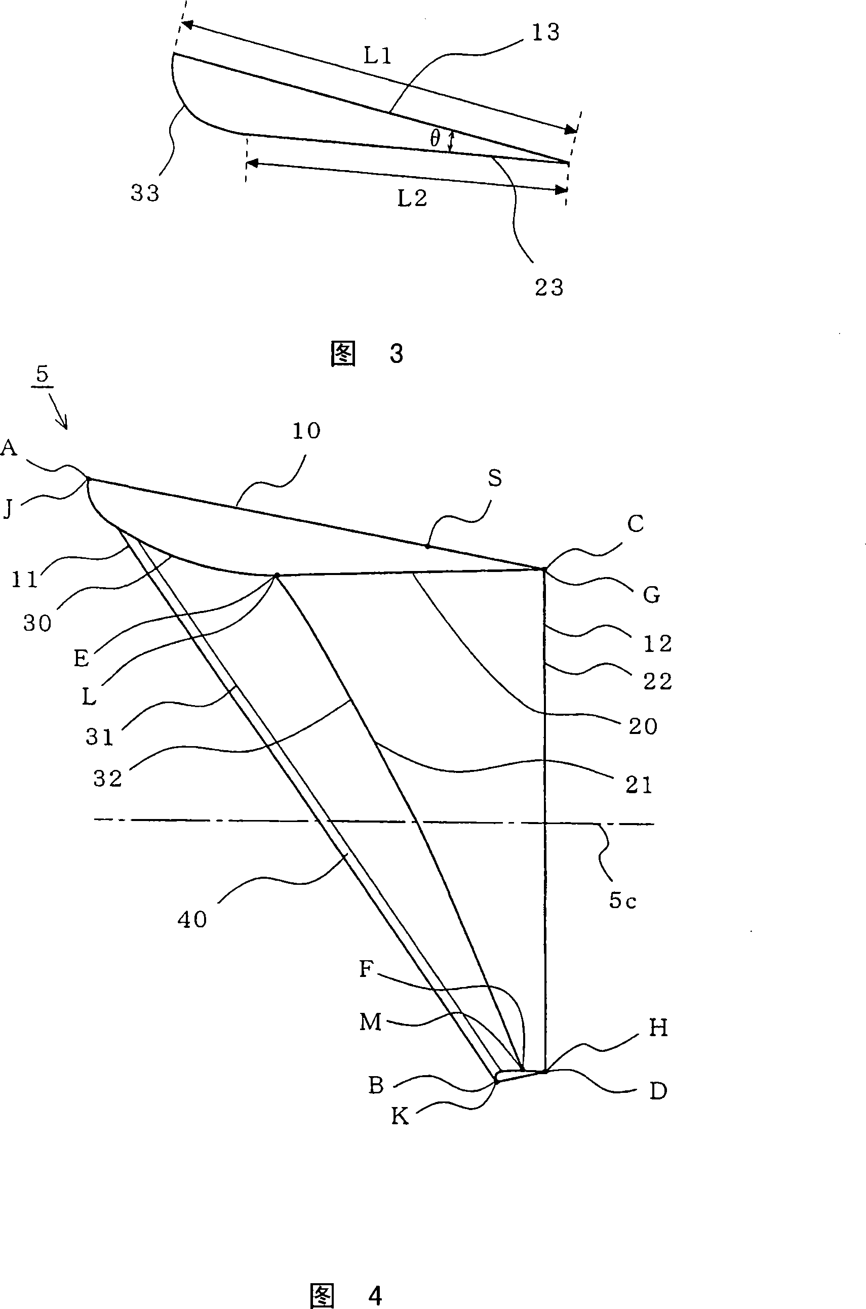
[0114] Fig. 4 is a side view showing an outline of a vessel conduit according to Embodiment 3 of the present invention. In FIG. 3 , the ship duct 5 is provided on a pipe body 40 along the bow side edge 11 of the duct outer plate 10 , and the bow side edge 31 of the bow side inner plate 30 is joined to the pipe body 40 . That is, it differs from the marine conduit 4 shown in Embodiment 2 ( FIG. 2 ) in that it has a pipe body 40 , and is the same as the marine conduit 4 in other respects. In addition, the same code|symbol is attached|subjected to the same part as Embodiment 2, and some description is abbreviate|omitted.
[0115] Therefore, the ship duct 5 exhibits the effect of the ship duct 4, and the joint of the duct outer plate 10 and the bow side inner plate 30 becomes easy, and the large curvature of the bow side edge portion 31 of the bow side inner plate 30 can be omitted. processing, so the manufacture of the bow s...
PUM
 Abstract
Description
Claims
Application Information
 - R&D
- Intellectual Property
- Life Sciences
- Materials
- Tech Scout
- Unparalleled Data Quality
- Higher Quality Content
- 60% Fewer Hallucinations
Browse by: Latest US Patents, China's latest patents, Technical Efficacy Thesaurus, Application Domain, Technology Topic, Popular Technical Reports.
© 2025 PatSnap. All rights reserved.Legal|Privacy policy|Modern Slavery Act Transparency Statement|Sitemap|About US| Contact US: help@patsnap.com


