
Motor vehicle heating system

A heater, automotive technology, used in lighting and heating equipment, heating/cooling equipment, vehicle components, etc., to solve problems such as unstable burners, no support, etc.

Inactive Publication Date: 2008-06-18
WEBASTO AG
View PDF0 Cites 1 Cited by
  • Summary
  • Abstract
  • Description
  • Claims
  • Application Information

AI Technical Summary

Problems solved by technology

Although the burner can start in these situations, however, when the glow plug goes out, i.e. no supporting energy is used to generate the (root) flame, the burner becomes unstable over time until it eventually goes out

Method used


Image

  • Motor vehicle heating system
  • Motor vehicle heating system
  • Motor vehicle heating system

Examples


Embodiment Construction

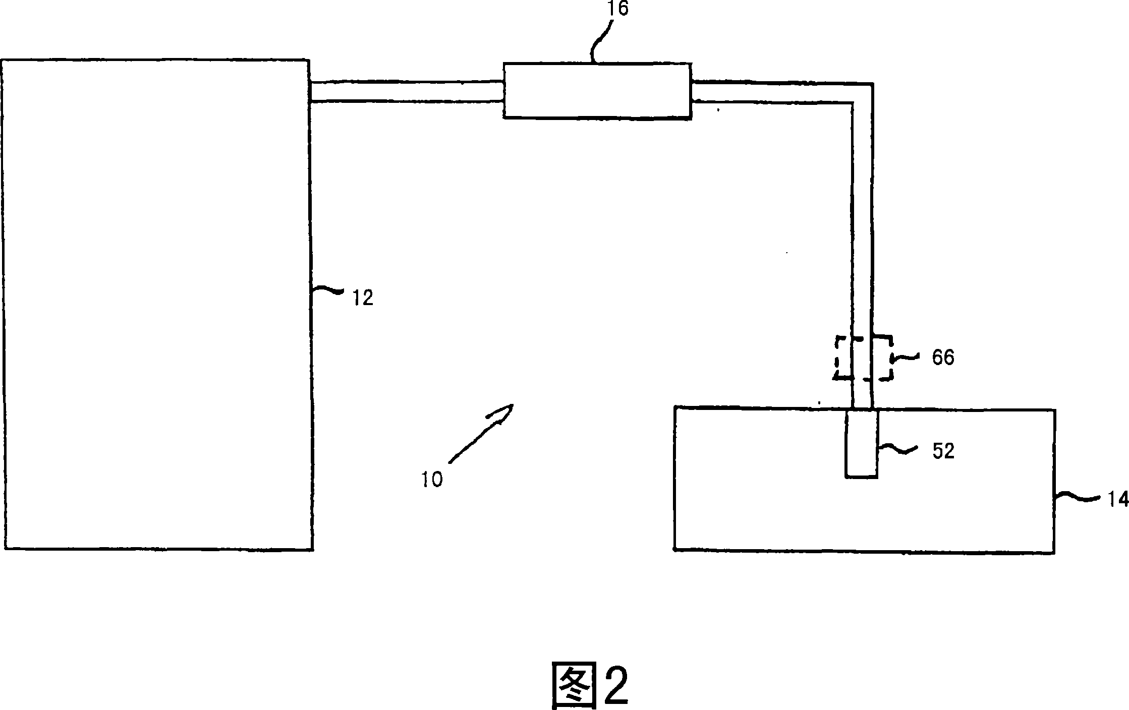
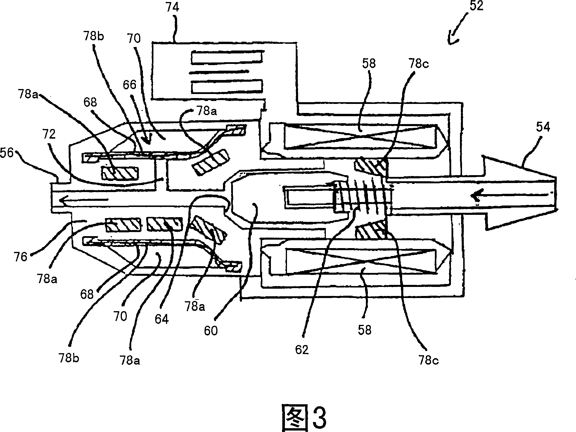
[0025] FIG. 2 shows a schematic block diagram illustrating an embodiment of the vehicle heater of the present invention. The vehicle heater 10 shown here can be a further heater or, for example, an auxiliary heater. The vehicle heater 10 shown here includes a reciprocating piston fuel pump 16 by means of which liquid fuel can be delivered from a fuel tank 12 to a burner / heat exchanger unit 14 . Depending on whether air heating or water heating is used, the burner / heat exchanger unit is connected to other air and / or water lines (not shown here), which are well known to those skilled in the art. The burner / heat exchanger unit 14 also comprises a fuel valve 52, by means of which the fuel supply can be partially or completely cut off. This fuel valve 52 does not have to be integrated in the fuel / heat exchanger unit 14 , but can actually also be arranged between the reciprocating piston fuel pump 16 and the burner / heat exchanger unit 14 .

[0026] The damping element 66 and the m...


PUM


Abstract

The invention relates to a motor vehicle heating system (10) which is embodied in such a way as to be operated by liquid fuel, and comprises a fuel pump (16 ; 16) and a damping element (34; 66) which is provided with an elastomer (36; 68) and used to damp pulsations generated by the fuel pump (16'; 16). According to the invention, means (58, 78a, 78b, 78c, 80, 82) are provided for heating the elastomer (68). Preferably, the motor vehicle heating system comprises an electromagnetically actuated fuel valve (52), and the damping element (66) is provided in the region of the electromagnetically actuated fuel valve (52) and especially integrated into the same.

Description

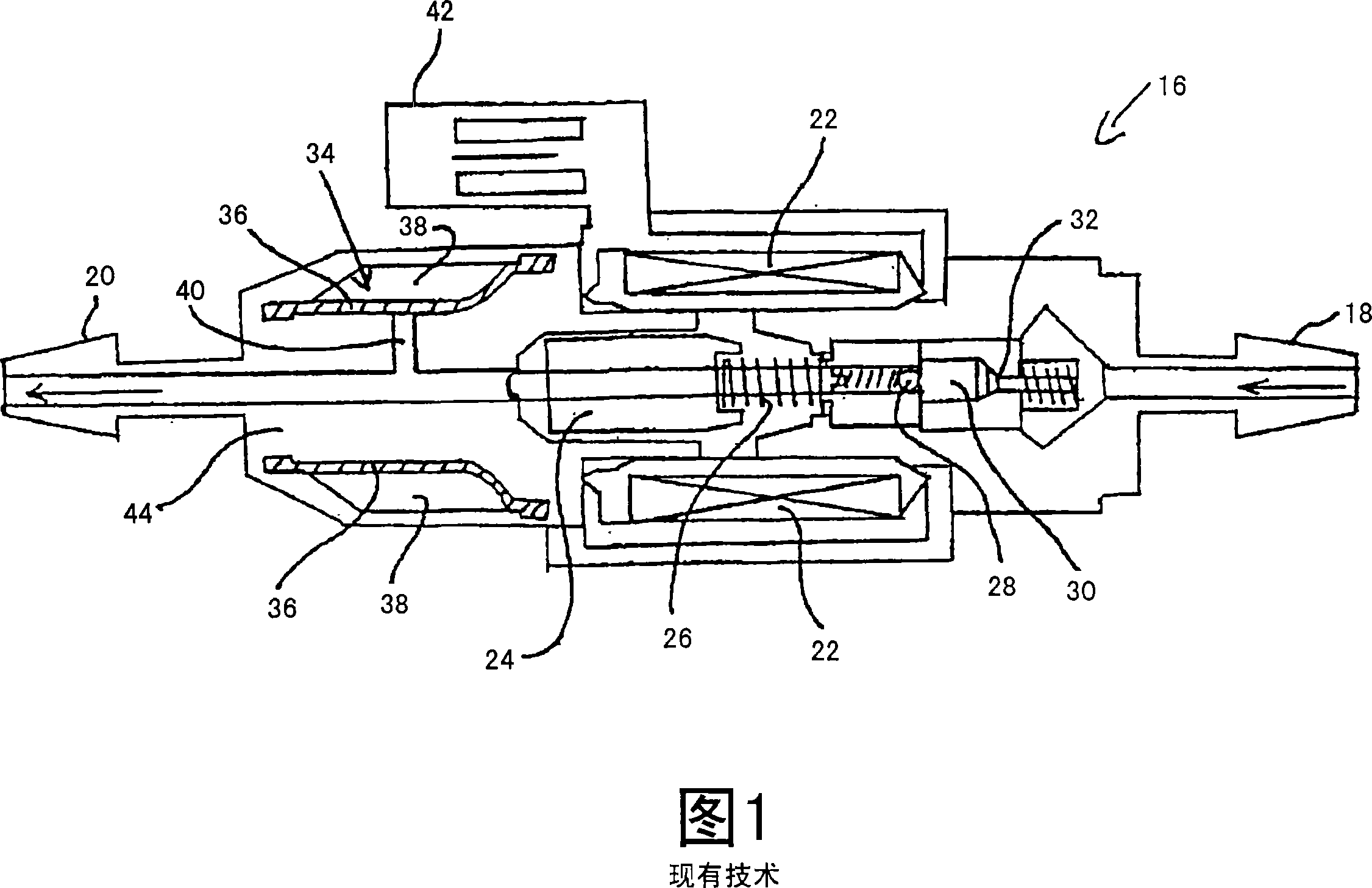
technical field [0001] The invention relates to a vehicle heater designed to operate on liquid fuel and having a fuel pump and a damping element comprising an elastomer for damping pulsations generated by the fuel pump. Background technique [0002] From the published documents Fahrzeug-und Verkehrstechnik, Technische Mitteilungen, vol.97 (2004) No.1 pages 9-11, for example, a reciprocating piston fuel pump is known, which generates pulsations in the fuel system during operation, and is shown in Fig. 1 schematically shows a cross-sectional view. [0003] The reciprocating piston fuel pump 16' shown in Figure 1 is arranged to deliver liquid fuel in the direction indicated by the arrow, i.e. from the fuel inlet 18 to the fuel outlet 20. Once a suitable voltage is applied to electrical terminals 42 , current flows through winding 22 , electromagnetically initiating movement through reciprocating piston 24 . First, the liquid fuel in the pump chamber 30 is expelled throug...

Claims


Application Information

Patent Timeline
IPC IPC(8): B60H1/22F23D11/44F02M53/06F02M55/04F02M51/06F02M61/16
CPCB60H1/2203B60H2001/2284F23K5/147F23K5/20F23K2301/20F23R2900/00001F23K2300/20B60H1/2206F23N1/005
Inventor V·施密特M·开普勒
Owner WEBASTO AG
Learn More