
Producing method forming and model hot enlarge fluorine plastic tube

A technology of a fluoroplastic tube and a manufacturing method, which is applied in the field of a manufacturing method and a forming die of a fluoroplastic tube with a flared horn-shaped nozzle, and can solve problems such as poor smoothness of the flared surface, foaming, and fracture at the flared portion, Achieve the effects of avoiding stress concentration and residue, easy installation and use, and avoiding stress concentration

Active Publication Date: 2008-06-25
CHENGDU AIRCRAFT INDUSTRY GROUP
View PDF0 Cites 13 Cited by
  • Summary
  • Abstract
  • Description
  • Claims
  • Application Information

AI Technical Summary

Problems solved by technology

The disadvantage of thermal flaring is that the height space of the drilling machine is small, the length of the tube is easily limited, and the wire of the heater is easily entangled when the spindle of the drilling machine is rotating, causing the heater to fail to work
Secondly, it is difficult to control the flaring temperature, the wall thickness of the flared bell mouth is uneven, the flaring surface is poor in smoothness, and it is easy to wrinkle, foam and produce water ripples.
However, PTFE plastic is different from metal and rubber pipes. Cold flaring will cause fracture at the flaring. On the other hand, due to its insolubility and infusibility, the melting temperature is higher than the decomposition temperature, so it cannot be used like PE, PP, PVC, etc. Thermoplastics achieve thermal expansion near their melting temperature

Method used


Image

  • Producing method forming and model hot enlarge fluorine plastic tube

Examples


Embodiment Construction

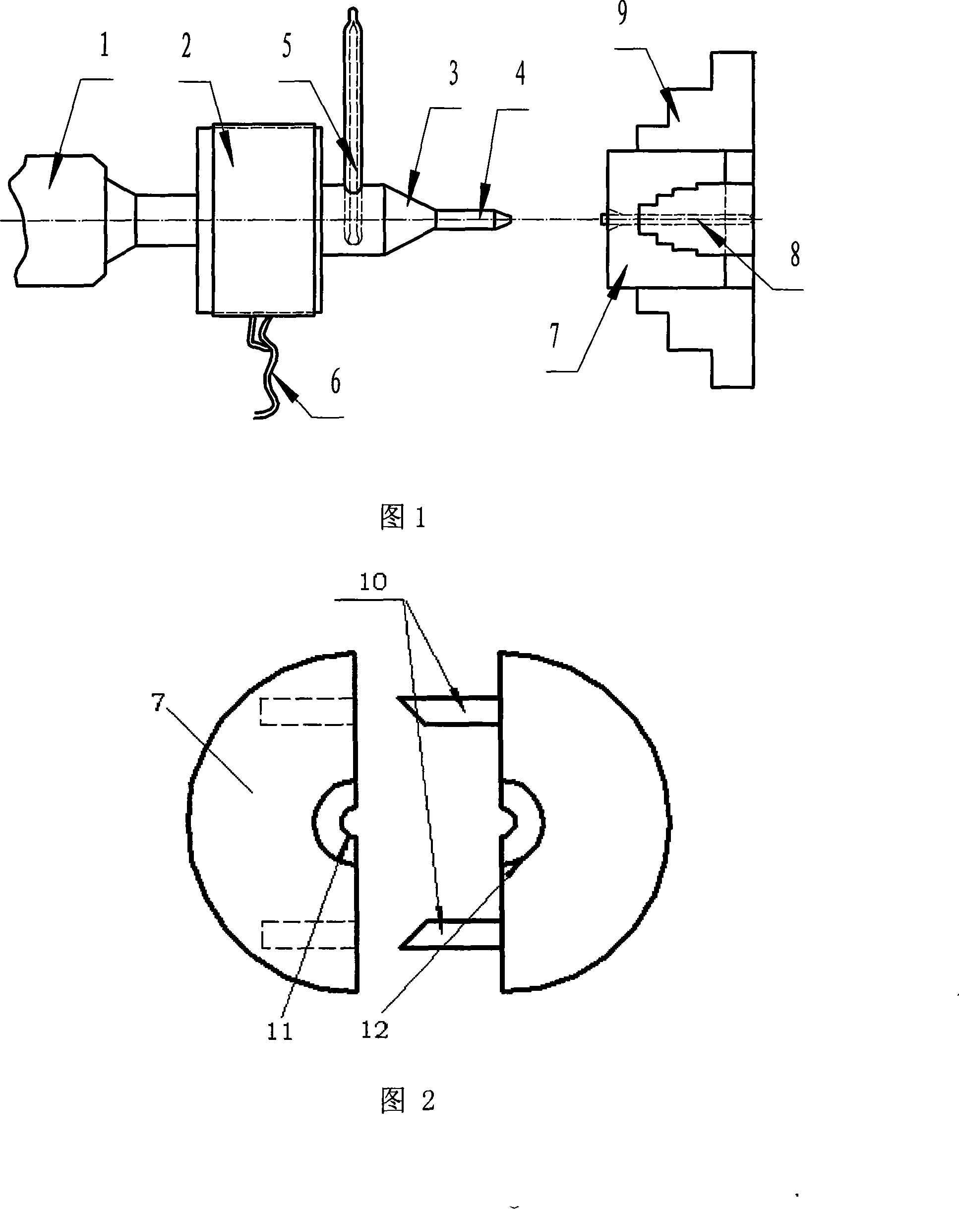
[0011] Figure 1 depicts a schematic diagram of the processing state of a thermally flared fluoroplastic tube composed of a heater, a temperature control device, and a claw plate of a machine tool. The whole system is composed of heating system, control system and mechanical system. The heating system is an electric heater, steam heater or oil heater, the control system includes a temperature sensor and a temperature control instrument, and the mechanical system is composed of a flaring fixture, a flarer and a lathe system. Its principle is: use a common lathe and a flare fixture, a new plastic flare method that rotates parts and feeds the flare to carry out plastic flare.

[0012] The punch expander and the flare die are on the same straight line, and the heater 2 is fixed on the central axis of the punch expander. The rear end of central axis cylinder is shaped on the connecting hole (not shown) of the top of suit common lathe. The heater 2 may be an electric heater, a stea...


PUM


Abstract

The invention relates to a preparation method and a molding mold of thermal flared end fluoroplastic pipe, which is that a flared end fluoroplastic pip is clamped in a mounting hole of a flared end cavity die with a trumpet flared end and rotates with a chuck of a lathe spindle; a male die expander with a heater and temperature control device is used for heating the head the flared end to flaring temperature and the head the flared end is fed through a lathe tail spindle to ensure that the fluoroplastic pipe is intenerated in rotating and tightly joined and matched with trumpet flared end of the flared end cavity die and cooled to form mold. The heater is fixedly connected on a the male die expander and electrically connected with the temperature control device controlled the temperature of the flared end; the flared end cavity die clamped in a rotator comprises two symmetrical clutch semicylinders is positioned on the same central line with the flared end head of flared end cavity die. The utility model takes advantage of the cold flow property of fluoroplastic to solve the defects that stress centralizes and leaves at the flared end, material is easily decomposed and the flared end is easily cracked. The invention ensures that the wall thickness of expanded trumpet flared end is more uniform and the surface of the flared end is smoother and avoids the occurrences of crinkle, forting and rippling.

Description

technical field [0001] The present invention relates to a manufacturing method and a forming die of a fluorine plastic tube with a thermally flared trumpet shape, more specifically, the present invention relates to a secondary thermally flared forming method for polytetrafluoroethylene plastic tubes and a thermally flared horn Forming die for tetrafluoroethylene plastic pipe with nozzle. The fluoroplastic pipe involved in the description of the present invention is only one type of plastic pipe fittings, but it can be considered that the present invention is suitable for various non-metallic plastic pipe fittings. Background technique [0002] In the known technology, whether the pipe fittings are metal pipes or rubber pipes, the flaring is to force the pipe to deform under the action of external force to form a trumpet shape at the nozzle, and the cold flaring technology at room temperature is used. The stress of cold flaring Concentrated, the material is easy to decompose...

Claims


Application Information

Patent Timeline
Patent Type & Authority Applications(China)
IPC IPC(8): B29C57/04B29C33/42B29C33/08B29K85/00
Inventor 何凯董华静薛丽莎蔡江海
Owner CHENGDU AIRCRAFT INDUSTRY GROUP
Learn More