Magnetic source power machine

A power machine and magnetic power technology, applied in the field of magnetic source power machines, can solve problems such as resource consumption and environmental impact, and achieve the effects of short manufacturing cycle, less investment and quick results

Inactive Publication Date: 2008-06-25
杜善敏
View PDF0 Cites 1 Cited by
  • Summary
  • Abstract
  • Description
  • Claims
  • Application Information

AI Technical Summary

Problems solved by technology

[0003] In order to solve the problems of consuming resources and affecting the environment in the prior art, the present invention provides a magnetic source power machine with less resource consumption and less impact on the environment

Method used


Image

  • Magnetic source power machine
  • Magnetic source power machine

Examples


Embodiment 1

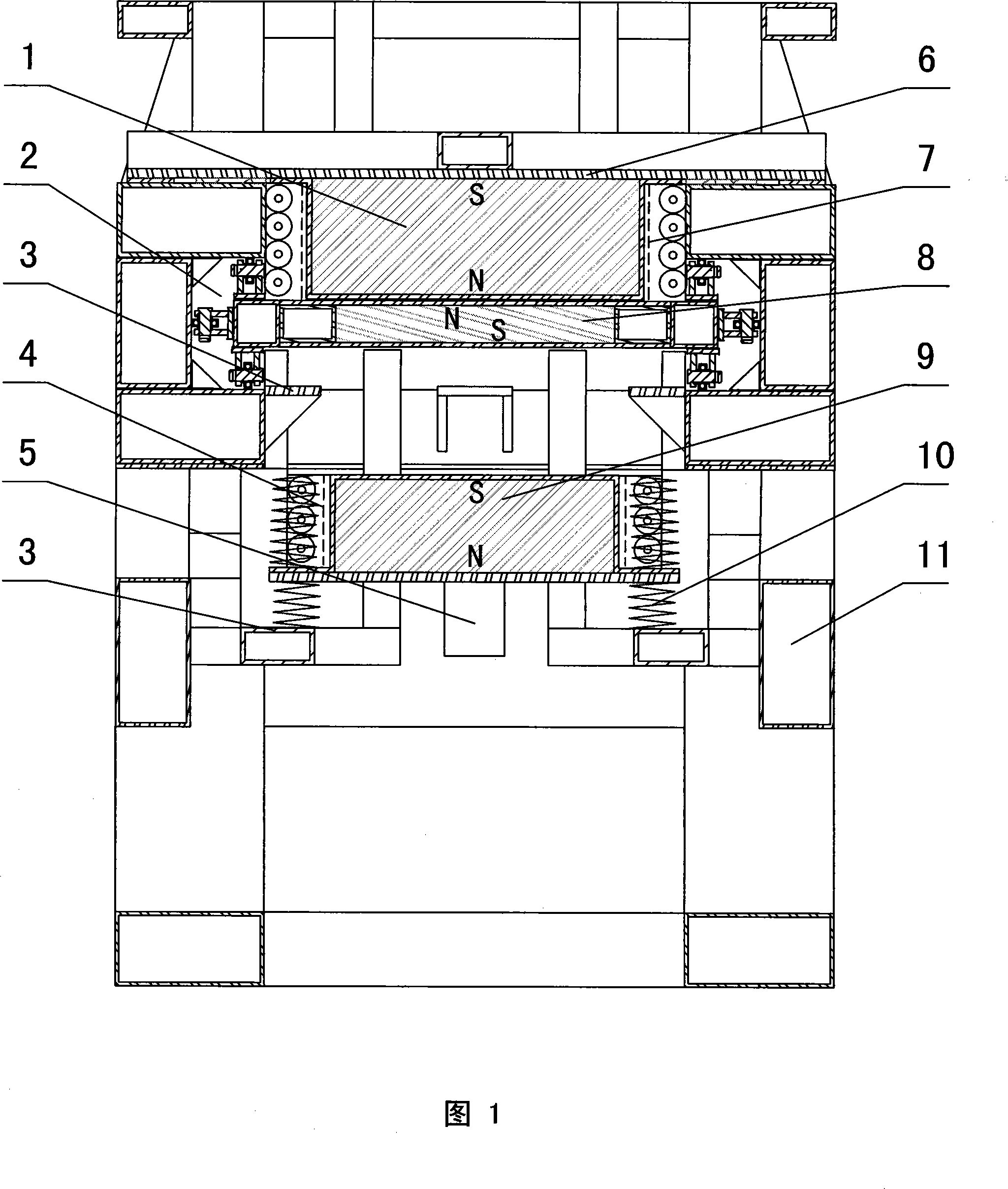
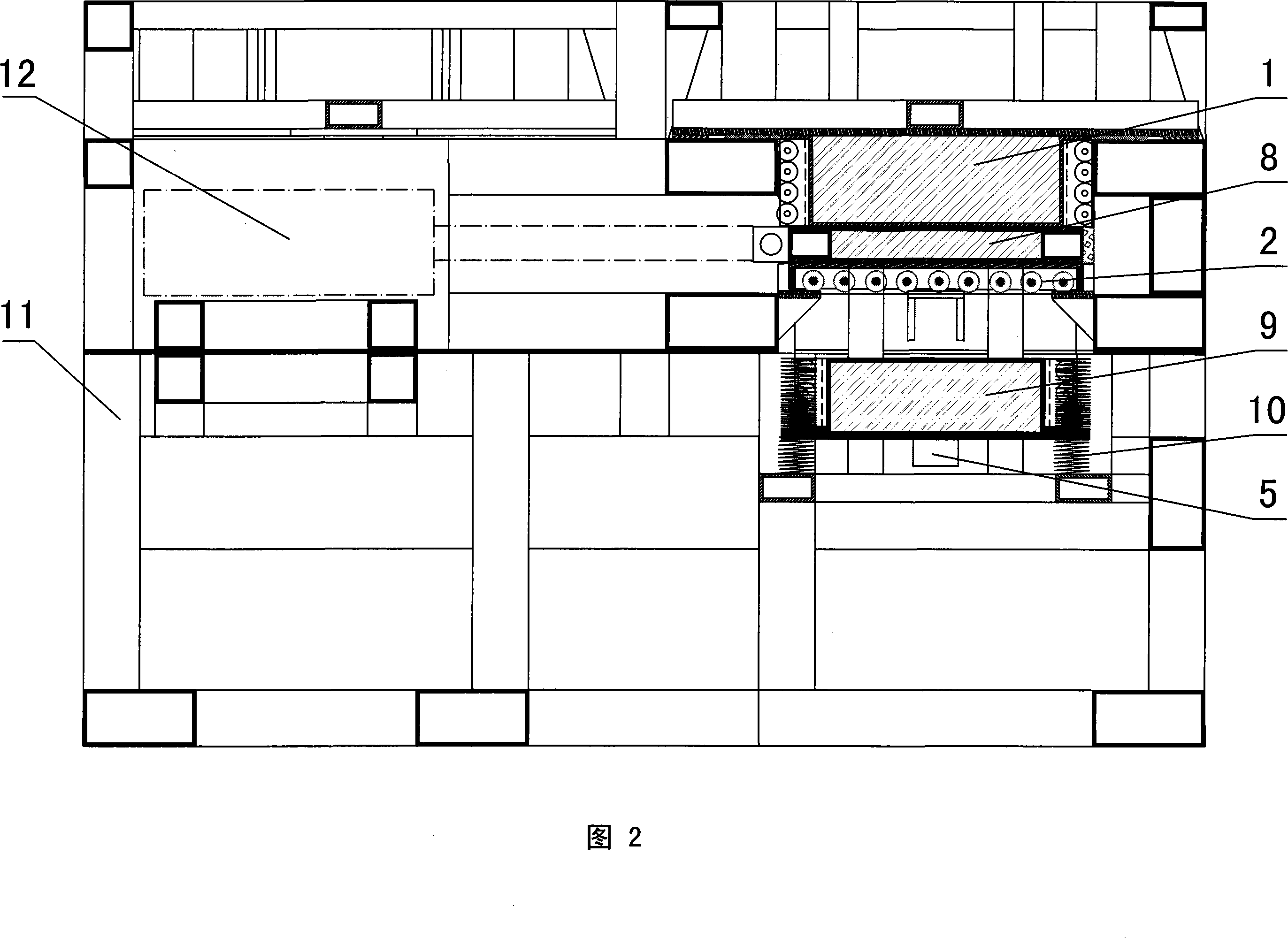
[0016] In the embodiment 1 shown in Figure 1 and Figure 2, the magnetic source power machine is composed of a frame 11, which is composed of a magnetic power group consisting of an upper magnet 1, a lower magnet 9 and a magnetic isolation plate 8, etc. The power groups are arranged in pairs, and a pneumatic starting device 12 is provided between the magnetic power groups, and the magnetic isolation plates 8 are connected to each other through the starting device. 8 out. The frame 11 is made of stainless steel with extremely low magnetic permeability. The frame 11 is provided with an upper slideway 7, a slideway 4 and a horizontal slideway 2. The upper magnet 1 is arranged in the upper slideway 7, and the lower magnet 9 is arranged in the slideway. In track 4, the upper and lower magnets are set with mutually attracting polarities. The magnetic isolation plate 8 is arranged in the horizontal slideway, and the polarities between the magnetic isolation plate 8 and the upper and ...

Embodiment 2

[0018] Upper magnet 1, lower magnet 9 and magnetic isolation plate 8 that embodiment 2 adopts are all electromagnets, and the insertion and extraction of magnetic isolation plate 8 are controlled by electric starting device 12, and all the other are the same as embodiment 1.

[0019] When the magnetic source power machine is working, the upper magnet and the lower magnet are respectively at the farthest points of the upper and lower slideways, and at the same time, the magnetic isolation plate is in a magnetic isolation state between the upper and lower magnets. Pull out the middle of the magnet, at this time the upper magnet slides to the lowest point of the upper slideway, the lower magnet moves up quickly along the slideway, and at the same time the upper end of the buffer spring starts to compress, when the buffer spring compression reaches the limit, the lower magnet reaches the rigidity of the upper end of the slideway Limiting device, this is the suction process of the u...


PUM


Abstract

The invention discloses a magnetic-source power machine which consists of a stander and a magnetic power group that is arranged on the stander and is composed of an upper magnet, a lower magnet and a magnetic-separation board, etc., wherein, the upper magnet is arranged inside an upper slipway, the lower magnet is arranged inside a lower slipway, the polarities of the upper and the lower magnets are arranged to be mutually attracted, the magnetic-separation board is arranged inside a horizontal slipway, the polarities of the magnetic-separation board and the upper and the lower magnets are arranged to be mutually rejected, a flexible limit device is arranged at the upper end of the upper slipway, rigid limit devices are arranged at the top end of the upper slipway and at two ends of the lower slipway, a buffer spring is arranged around the lower slipway, the buffer spring is connected with the lower magnet, and the lower end of the lower magnet is connected with a power output mechanism. The invention effectively resolves the problems of the prior power equipment such as waste and loss of the energy and environment influence. The invention has the remarkable advantages that the manufacturing period is short, the capital investment is less, the effect is achieved rapidly, the magnetic-source power machine is free from any environmental pollution, etc.

Description

technical field [0001] The invention relates to a power machine, in particular to a magnetic source power machine which fully utilizes magnetic energy. Background technique [0002] At present, electricity production is mainly divided into thermal power, hydropower, nuclear power, and wind power. Nuclear power has the characteristics of huge investment, long construction period, and large area. Although thermal power has a short construction period and quick results, the pollution to the environment is also obvious. The construction of hydroelectric dams has also caused some damage to the ecological balance. Although wind power has quick results, low investment, and little impact on the environment, it also has the characteristics of large area and long investment recovery period. In addition, the construction and maintenance of transmission lines and equipment will invest a lot of social resources. To sum up, while electricity production provides energy to the society, i...

Claims


Application Information

Patent Timeline
Patent Type & Authority Applications(China)
IPC IPC(8): H02N11/00
Inventor 杜善敏
Owner 杜善敏
Why Eureka
Try Eureka