Power controller assembly and method

A power control and controller technology, which is applied in the direction of temperature control, electrical components, and electrical equipment construction parts using electric methods, can solve the problem of not changing the set point temperature of thermal applications

Active Publication Date: 2008-06-25
WATLOW ELECTRIC MFG
View PDF0 Cites 7 Cited by
  • Summary
  • Abstract
  • Description
  • Claims
  • Application Information

AI Technical Summary

Problems solved by technology

[0009] Existing systems also often have limited in-operation reprogrammability and do not provide for

Method used


Image

  • Power controller assembly and method
  • Power controller assembly and method
  • Power controller assembly and method

Examples


Embodiment Construction

[0055] The following description is merely exemplary in nature and is not intended in any way to limit the invention, the disclosure or its application or uses.

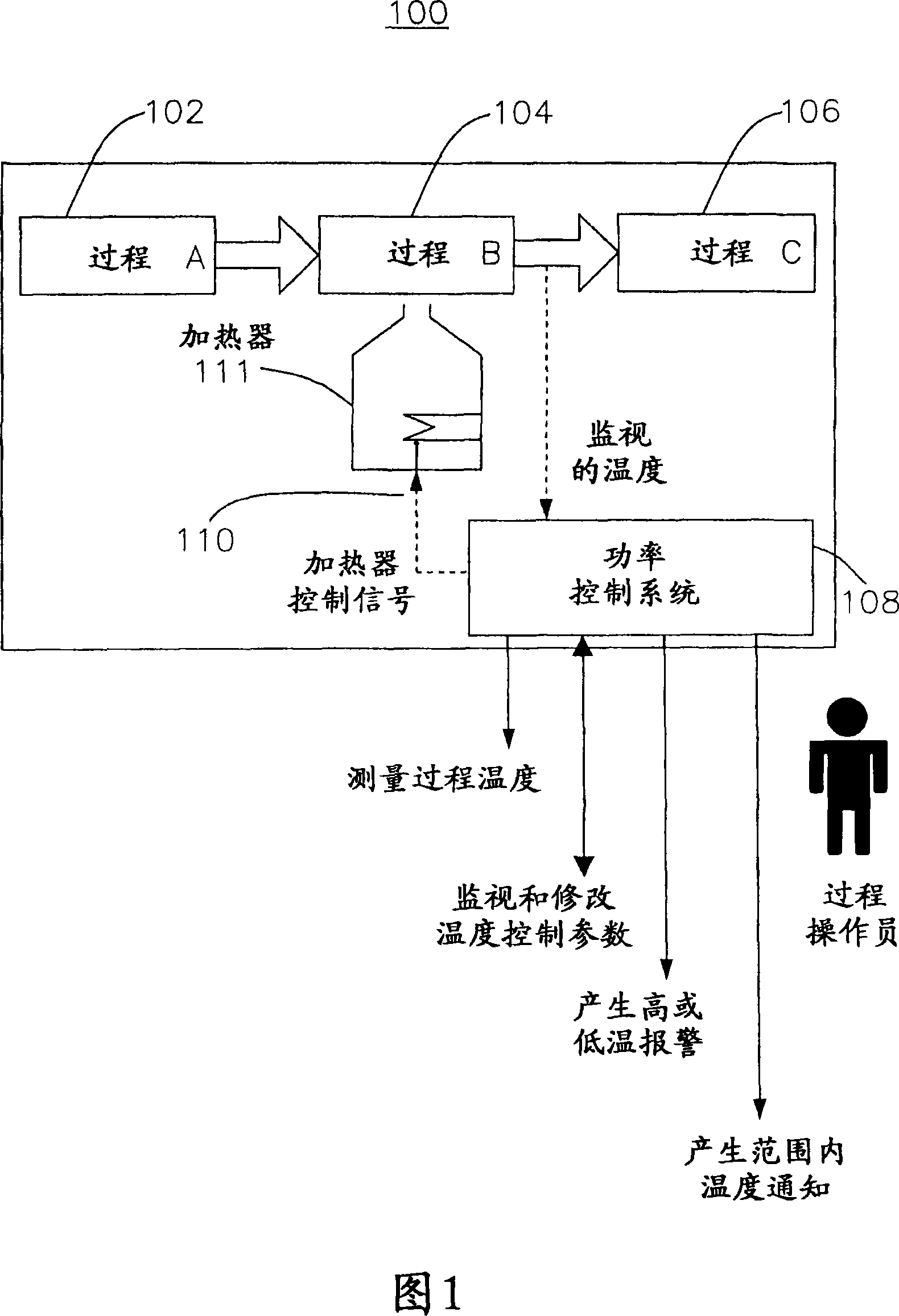
[0056] (power controller operating environment)

[0057] FIG. 1 illustrates, by way of example, a power control system environment 100 suitable for one or more of the various embodiments of the present disclosure. In FIG. 1 , the heat process contains three processes A 102 , B 104 , and C 106 , with process B 104 requiring heating of the material before proceeding to process C 106 . Such exemplary manufacturing process 100 may include plastic or semiconductor manufacturing processes as examples. In this example, the temperature of Process B 104 is monitored by a sensor (not shown), and the monitored temperature is provided in a sensor signal to a power controller or power control system 108 . The power control system receives the monitored temperature and generates a heater control signal 110 , which may be in the ...


PUM


Abstract

The present invention relates to power controller assemblies and methods. The power control system has a controller housing, a power switch disposed within the controller housing for selectively providing power from a power source to an electrical load, a limiter disposed within the controller housing configured to provide a limit switch function in response to a threshold limit, and a controller disposed within the controller housing and configured to control one or more operations of the control system. The controller housing may include a housing having a securing portion located adjacent the opening for securing a portion of the connector when coupled with the coupler. An electronics mount for a power controller or any other electronic device may include brackets and couplers. The bracket has a mounting flange configured to attach to a surface within the operating environment, a securing flange, and a plurality of securing tabs offset from the surface and located around an outer edge of the surface. The bracket includes an offset portion coupling the mounting flange to the fixed surface and defining an offset therebetween. The coupler is configured to be secured to the securing flange. The bracket and coupler are configured to releasably couple with less than one full turn.

Description

technical field [0001] The present invention relates to power control systems, and more particularly, the present invention relates to power controllers for use in control systems having enclosures. Background technique [0002] The statements in this section merely provide background information related to the present disclosure and may not constitute prior art. [0003] In general, typical power control devices require discrete component selection, custom mounting and wiring for each component and feature and numerous connections. In addition, any changes, additions, modifications and replacements require disconnection and reconnection of various leads, again increasing the chance of wiring errors. As a result, existing power control devices are often complex and expensive to install. This complexity and cost also limits their application, or often the functionality included in specific user applications. For example, limit control, overvoltage or power monitoring compo...

Claims


Application Information

Patent Timeline
IPC IPC(8): G05D23/19H01H37/00
CPCG05D23/19H05K7/1471H05K7/1474H05K5/0204H01H37/00
Inventor 威廉·C·伯灵格库特·W·彼得森德尔·T·沃夫詹姆斯·P·翰特格斯詹姆斯·H·科瑞瑟尔科蒂斯·A·福斯特艾瑞克·E·艾利斯
Owner WATLOW ELECTRIC MFG
Why Eureka
Try Eureka