
Gravity bulkhead design method based on earthquake displacement

A design method and retaining wall technology, applied in calculation, infrastructure engineering, water conservancy engineering, etc., can solve the problem of not considering the sliding displacement and rotational displacement of the wall, the large difference in the allowable displacement of the design of the retaining wall, and insufficient displacement estimation Impact and other issues

Inactive Publication Date: 2008-07-02
HARBIN INST OF TECH
View PDF0 Cites 8 Cited by
  • Summary
  • Abstract
  • Description
  • Claims
  • Application Information

AI Technical Summary

Problems solved by technology

[0004] The purpose of the present invention is to provide a design method of gravity retaining wall based on seismic displacement, which can solve the problem that the existing retaining wall seismic design method does not consider the sliding displacement and rotational displacement of the wall or only considers the sliding of the wall Displacement without considering the rotational displacement, resulting in a large difference between the design permissible displacement of the retaining wall and the actual displacement, and the problem of excessive displacement and insufficient displacement estimation affecting the use function of the retaining wall

Method used


Image

  • Gravity bulkhead design method based on earthquake displacement
  • Gravity bulkhead design method based on earthquake displacement
  • Gravity bulkhead design method based on earthquake displacement

Examples


specific Embodiment approach 1

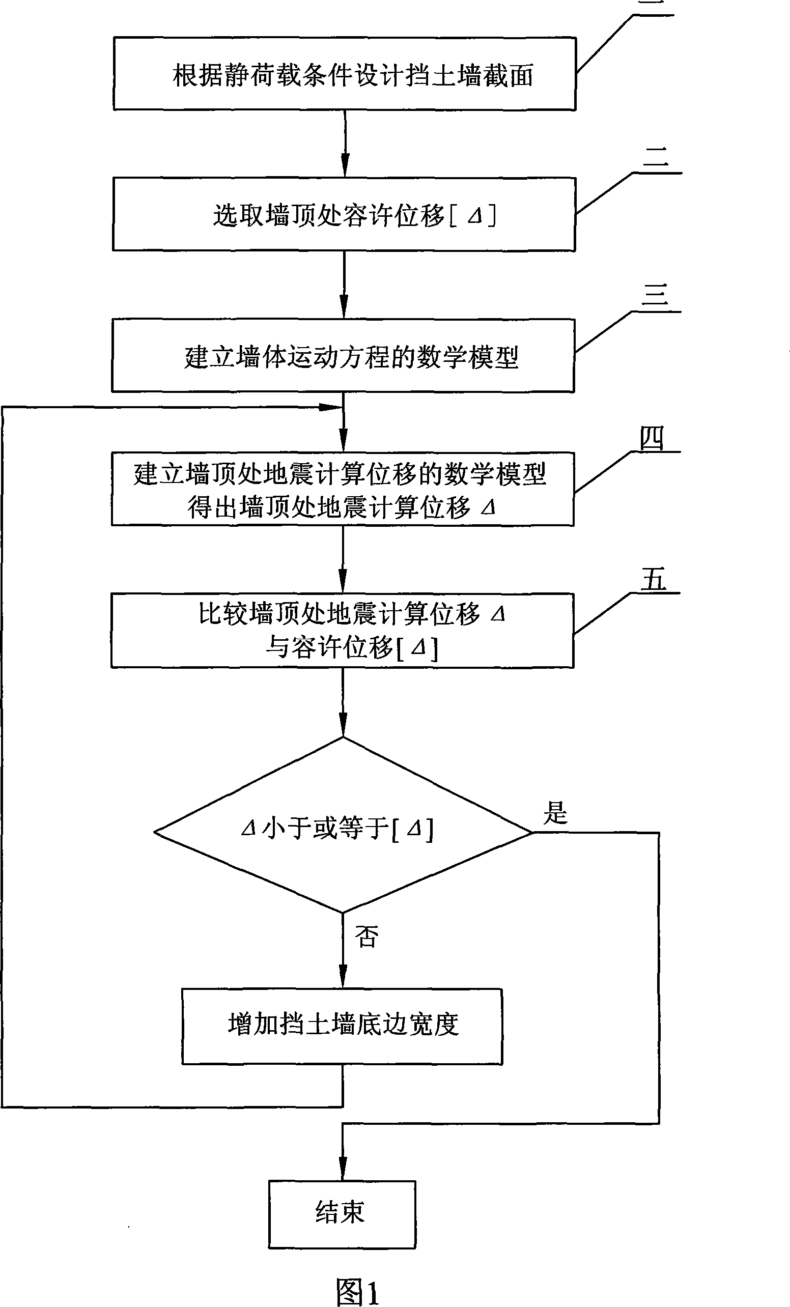
[0026] Specific embodiment one: the design method of the gravity type retaining wall based on earthquake displacement of the present embodiment is realized according to the following steps:

[0027] Step 1. Design the retaining wall section according to the static load condition;

[0028] Step 2. Select the allowable displacement at the top of the wall as [Δ]=300 k h (unit: mm), where k h is the horizontal seismic coefficient; the [Δ]=300·k h It is determined in accordance with the relevant recommendations of the European specification Eurocode-8;

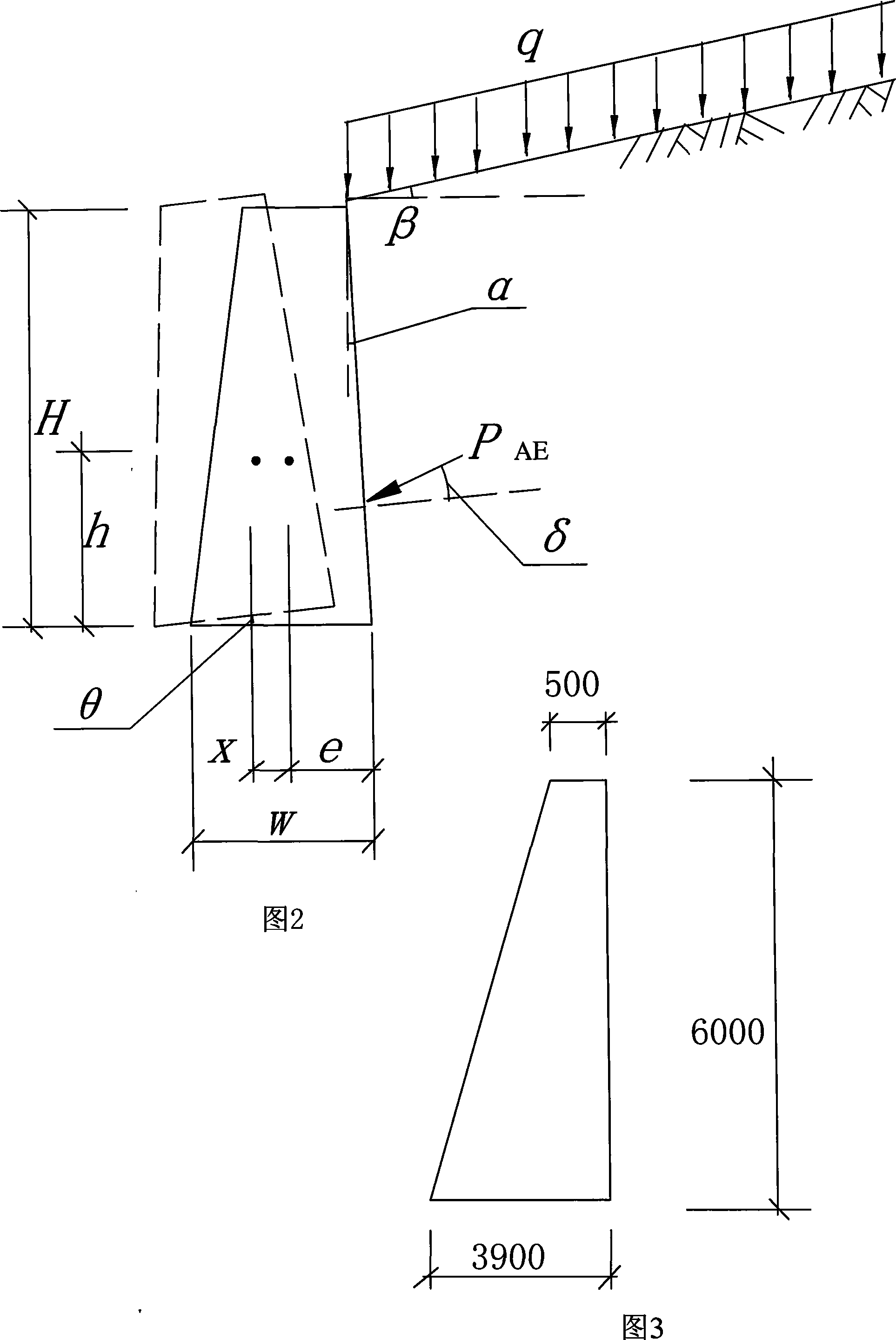
[0029] Step 3. Establish the mathematical model of the wall motion equation, and calculate the wall rotation angle θ and horizontal sliding displacement x by numerically integrating the wall motion equation. The wall motion equation is as follows:

[0030] m mh mh I ...

specific Embodiment approach 2

[0043] Specific implementation mode 2: In this implementation mode, in step 5, the width w of the bottom edge of the retaining wall is increased by 300mm. Compare the earthquake calculated displacement Δ and the allowable displacement [Δ] at the top of the wall. If the calculated displacement exceeds the allowable displacement, increase the width w of the bottom edge of the retaining wall by 300mm and then return to the previous step to calculate, which can quickly achieve the design goal and reduce the number of checking calculations . When the width w of the bottom edge of the retaining wall increases, the mass m of the wall, the moment of inertia I of the wall, and the height h of the center of gravity of the wall should all be recalculated, which is the basic common sense of those skilled in the art. Other steps are the same as in the first embodiment.

specific Embodiment approach 3

[0044] Specific embodiment three: as shown in Figure 3, use the section of retaining wall designed by the present invention method, when the top width of retaining wall is 500mm, and when the height of wall is 6000mm, finally calculate the bottom edge width of retaining wall to be 3900mm. The plain concrete gravity retaining wall is 6m high and the wall weight is 25kN / m 3 , foundation soil weight 19kN / m 3 , internal friction angle 35°, void ratio 0.45, water content 10%, Poisson's ratio 0.3; fill weight 22kN / m 3 , the internal friction angle is 33°, the cohesion force is 11kPa, the wall-soil friction angle is 22°; the allowable displacement of the top of the wall is 0.10m. The section size is designed according to the static condition, and the width of the bottom is 3.6m; the synthetic acceleration record is input at the base, and the calculated seismic displacement is 0.15m, which is greater than the allowable displacement; the bottom is enlarged by 0.3m and modified to 3.9m...


PUM


Abstract

A weight-type retaining wall design method based on earthquake displacement relates to a retaining wall design method. The invention resolves the following problems in prior retaining wall aseismatic design methods: Not considering of the slide displacement or the rotary displacement of wall bodies; or only considering the slide displacement, but not of the rotary displacement of wall bodies, so that design allowance displacement of retaining walls is by far different from actual displacement; as well as two big displacement or insufficient estimation on the displacement, so as to influence utilization functions of retaining walls. Main steps of the invention are as follows: Design the section of a retaining wall and take the allowable displacement at the wall top, so as to establish the mathematical module for the wall body motion equation; establish the mathematical module of the earthquake calculate displacement at the wall top; compare the earthquake calculate displacement delta at the wall top against the allowable displacement [DELTA]. The invention overcomes the shortcomings in prior design methods that only considering of horizontal slide displacement of wall bodies, but not of the insufficiency of cohesion force on backfilled soil; the motion equation considers of the coupling movement between the slide displacement and rotation for the wall bodies, so that the method is suitable for more expansible working conditions and more closes to engineering facts.

Description

technical field [0001] The invention relates to a design method of a retaining wall. Background technique [0002] The general seismic design of retaining walls adopts the pseudo-static method, which converts ground motion into inertial force for stability checking, and ensures the seismic safety of the wall-soil system by controlling the safety factor. This method cannot estimate the displacement of the wall under the action of the earthquake, and the limit value of the safety factor is mostly determined by experience. It is not clear how much the safety factor corresponds to the displacement. In order to ensure that excessive displacement does not occur, the limit value of the safety factor can only be increased. Obviously, in the absence of the relationship between the earthquake action and the final displacement of the retaining wall, it is not economical to simply increase the weight of the wall to increase the safety factor, and it is also difficult to ensure that no ...

Claims


Application Information

Patent Timeline
IPC IPC(8): G06F17/50E02D29/02
Inventor 陶夏新王福彤陈宪麦陈学良
Owner HARBIN INST OF TECH
Learn More