Analyzer

一种分析仪、分析物的技术,应用在分析仪领域,能够解决旋转板控制复杂、频繁更换滤光片等问题

Active Publication Date: 2008-07-02
SYSMEX CORP
View PDF0 Cites 19 Cited by
  • Summary
  • Abstract
  • Description
  • Claims
  • Application Information

AI Technical Summary

Problems solved by technology

[0004] Conventional analyzers had the problem of being difficult to replace filters frequently in a short period of time due to the need to repeatedly rotate and stop the rotating plate
In addition, when switching filters, it is necessary to rotate and stop the rotating plate repeatedly, which also causes complicated problems in the control of the rotating plate

Method used


Image

  • Analyzer
  • Analyzer
  • Analyzer

Examples


no. 1 approach

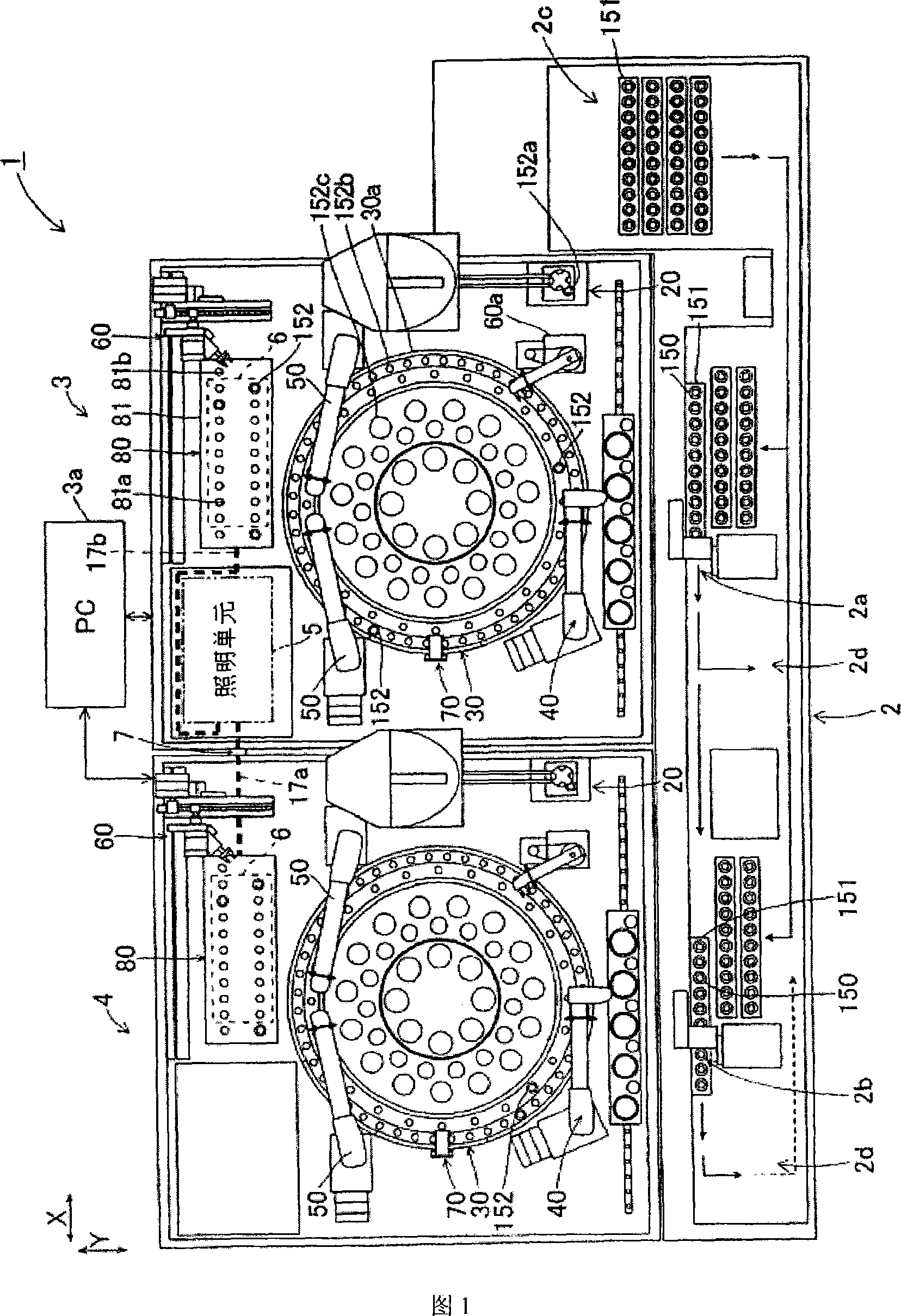
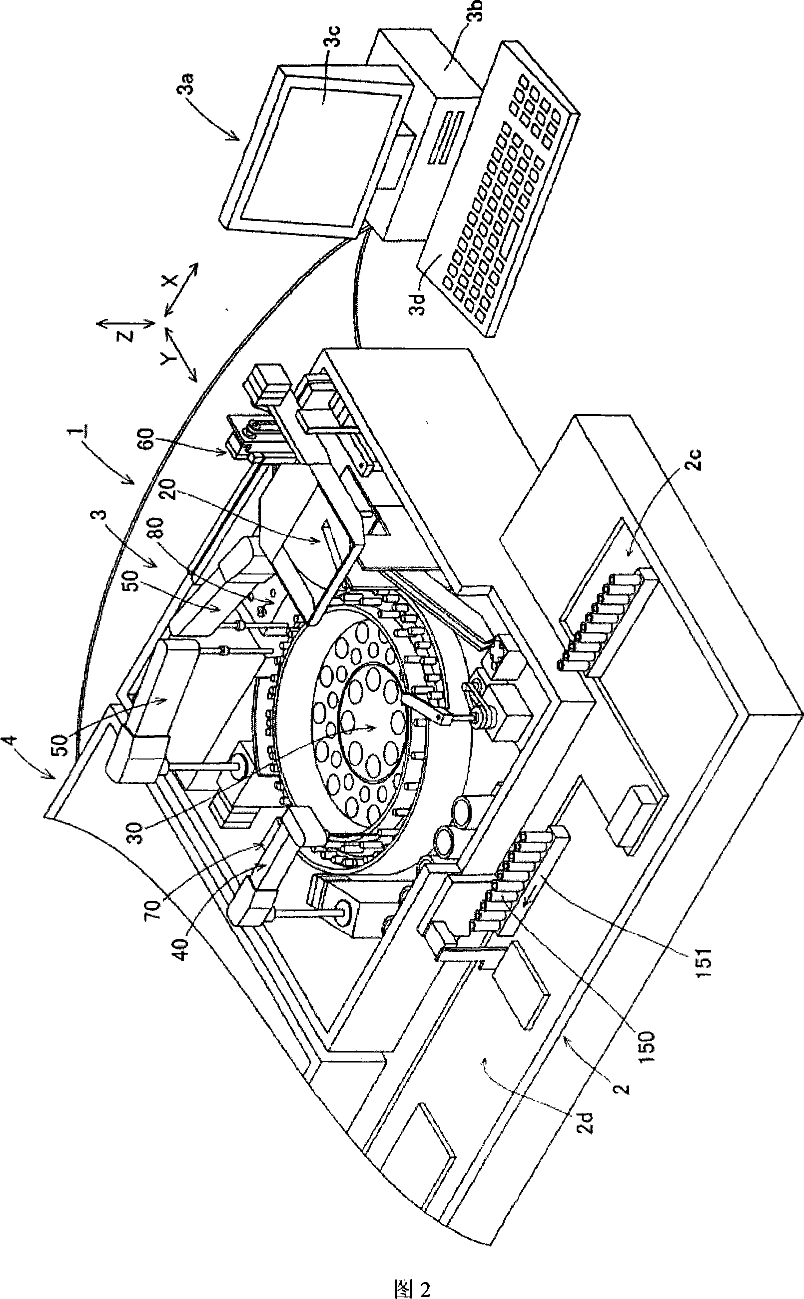
[0041] First, the configuration of an analysis system 1 according to a first embodiment of the present invention will be described with reference to FIGS. 1 to 12 .

[0042] The analysis system 1 according to the first embodiment of the present invention is a system for optically measuring and analyzing the amount and activity level of a specific substance related to blood coagulation and lineolysis functions, and plasma is used as a sample. The analysis system 1 of the first embodiment performs optical measurement of a specimen by the coagulation time method. The coagulation time method employed in the first embodiment is a measurement method for detecting the coagulation process of a specimen as a change in transmitted light.

[0043] The configuration of the analysis system 1 can be changed according to the scale of the installed facilities. For example, when installed in a facility with a small number of samples, the analysis system 1 is composed of an analysis device 3 a...

Embodiment approach

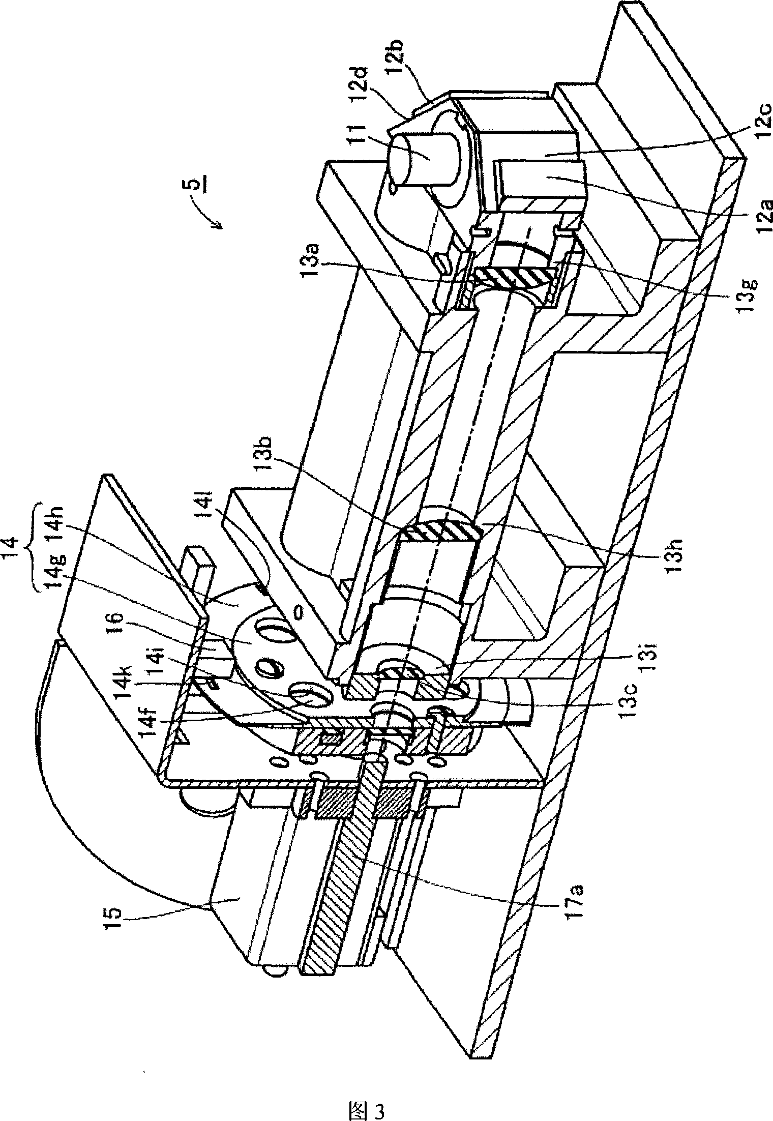
[0141] In the first embodiment, as mentioned above, the optical filter 14 having five different optical filters 14b-14f is substantially rotated at a constant speed, and it is not necessary to stop the optical filters 14b-14f on the optical path of the light source of the halogen lamp 11, Therefore, it is not necessary to adjust the position of the optical filters 14b to 14f on the optical path with respect to the light source of the halogen lamp 11 . Since it is not necessary to stop the optical filters 14b-14f on the light path of the light source of the halogen lamp 11, and it is not necessary to use an expensive motor with a high positioning degree, an inexpensive analysis device can be provided.

[0142] In the first embodiment, as described above, the photoelectric conversion element 84a detects the light emitted by the illumination unit 5 illuminating the analyte, and at the same time outputs a signal corresponding to the detected light, and the PC host 3b analyzes the l...

no. 2 approach

[0154] Next, the operation of the analysis system according to the second embodiment of the present invention will be described. The configuration of the analysis system of the second embodiment is the same as the configuration of the analysis system 1 of the above-mentioned first embodiment, so description thereof will be omitted. The analysis system of the second embodiment is different from the analysis system 1 of the above-mentioned first embodiment in that the control unit 112 does not use the differential signal of the reference signal to obtain data, but the optical filter 14 slit detection signal to obtain data.

[0155] Next, the initial setting of the analysis system of the second embodiment will be described. The analysis system of the second embodiment calculates the number p of clocks elapsed from the detection of the slit to the start of data acquisition as follows. Fig. 26 is a flowchart of p clock calculation processing by the controller of the second embodim...


PUM


Abstract

An analyzer is provided with a light irradiation device. The light irradiation device includes a light source, and a rotatable filter section, which has a plurality of optical filters having different light transmission characteristics, and irradiates an analyzing object with light that passed through the optical filters arranged in a path of the light from the light source while the filter section is rotating, by successively switching the optical filters by rotating the filter section. The analyzer is also provided with an analyzing means for analyzing characteristics of the analyzing object, based on optical information obtained from the analyzing object irradiated with the light by the light irradiation device while the filter section is rotating.

Description

Technical field: [0001] The present invention relates to an analyzer, in particular to an analyzer with an optical filter arranged on the optical path of a light source and an illuminating device for irradiating the light passing through the optical filter onto an analyte. Background technique: [0002] Optical analyzers used for biochemical examinations, blood coagulation examinations, etc., have hitherto been known as analyzers having an illumination device that can replace the filter placed on the optical path of the light source according to the characteristics of the reagent used for analysis, the analysis method, etc. , to irradiate the analyte with light having a certain wavelength characteristic (for example, refer to Patent Publication No. 2003-83884). In the past analyzer published in the above-mentioned Patent Publication No. 2003-83884, the optical filter arranged on the optical path of the light source is replaced by rotating the rotating plate provided with sev...

Claims


Application Information

Patent Timeline
Patent Type & Authority Applications(China)
IPC IPC(8): G01N21/27G01N21/82
CPCG01N21/31G01N21/253G01N21/82G01N35/025G01N2021/3174G01N2021/825G01N2201/0826
Inventor 德永一敏山本典正
Owner SYSMEX CORP
Why Eureka
Try Eureka