Vacuum box heat collection water storage integral solar water heater device

A solar water heater and vacuum heat collection technology, applied in the field of solar energy applications, can solve problems such as roofs, long pipelines, difficult maintenance, etc., and achieve the effects of flexible placement, reduction of environmental pollution, and installation safety.

Inactive Publication Date: 2008-07-09
北京九艺通文化艺术有限公司
View PDF0 Cites 3 Cited by
  • Summary
  • Abstract
  • Description
  • Claims
  • Application Information

AI Technical Summary

Problems solved by technology

The common problems are: first, it is difficult to maintain; second, it is not beautiful; third, the heat of the heat collector cannot be kept warm, and the thermal efficiency is affected; fourth, the use is limited, and it is difficult for families on the ground floor to use it, even if it is used, it can only be used on the roof. The pipeline is too long, and the heat loss is large

Method used


Image

  • Vacuum box heat collection water storage integral solar water heater device
  • Vacuum box heat collection water storage integral solar water heater device

Examples


Embodiment 1

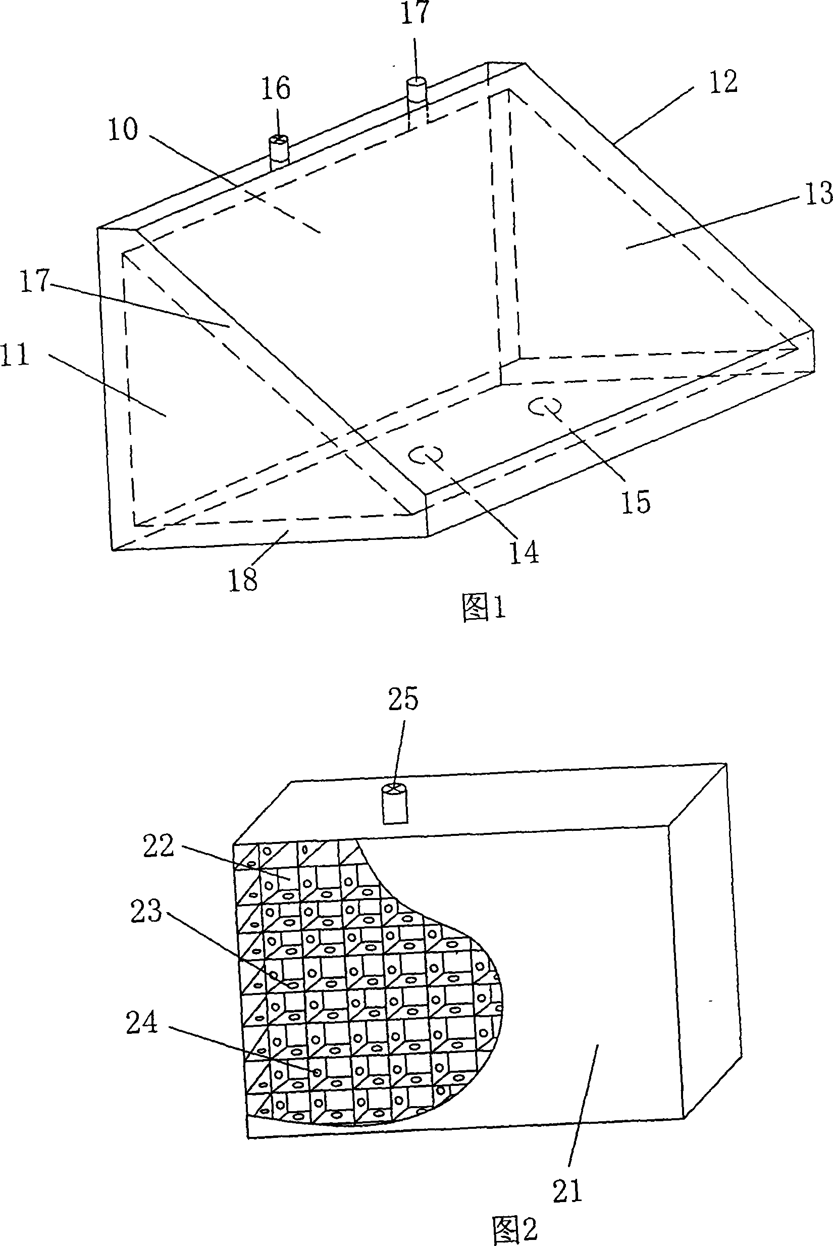
[0026] The structure of Embodiment 1 is shown in Figure 1. The device is a box body with two layers of box walls whose longitudinal section is a right angled triangle. The inner box walls form a water storage cavity 10. It is a right triangle, and the end face of the box body that can be exposed to sunlight includes a front panel 13 and two end panels; Three interconnected vacuum heat collecting layers 17 are formed among them. The outer wall panels of each vacuum heat collecting layer are transparent plates, and the outer surface of the corresponding inner box wall panels is coated with a gradient aluminum nitrogen aluminum film; other inner and outer boxes The walls are filled with insulating material to form an insulating layer 18; the lower end surface of the device is provided with a hot water outlet pipe interface 14 and a cold water inlet pipe interface 15 that are directly connected to the water storage cavity; Vacuum layer and the vacuumized valve 16 and explosion-pro...

Embodiment 2

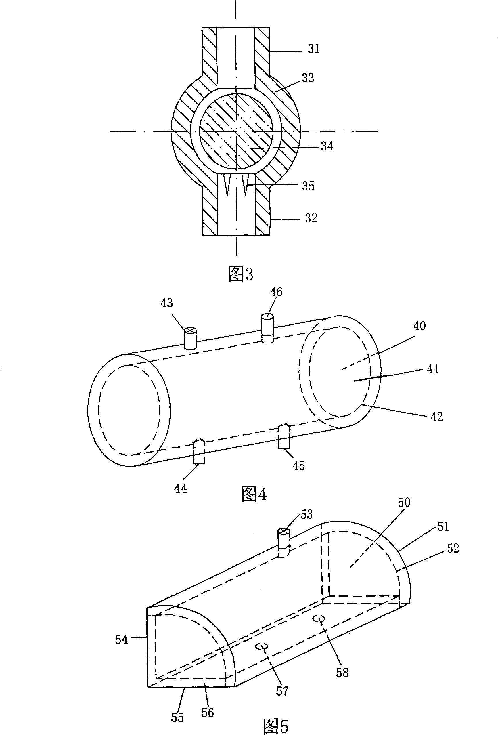
[0030] The structure of Embodiment 2 is shown in Figure 4. The device is a barrel-shaped body with two walls with a circular longitudinal section. The inner barrel forms a water storage cavity 40, and the outer wall of the inner barrel is coated with a gradient aluminum nitrogen aluminum film. , the outer barrel wall is a transparent material, and a vacuum heat-collecting layer is formed between the inner barrel and the outer barrel, and the inner and outer barrel walls 41, 42 are connected with an annular grid rib, and the grid rib is provided with a through hole (not shown in the figure). shown), the gap between the two layers of box walls is connected, and a vacuum valve 43 is set on the upper end of the outer barrel wall of the vacuum heat collecting layer, and the space between the two layers of box walls is The air is drawn out to form a vacuum heat-collecting layer; a hot water outlet pipe interface 44 and a cold water inlet pipe interface 45 that are directly connected ...

Embodiment 3

[0032] The structure of Embodiment 3 is shown in Figure 5. The device is a box body with two layers of walls combined with a flat plate and an arc-shaped plate. Its longitudinal section is a D-like figure surrounded by two vertical lines and a section of arc. , the inner box constitutes a water storage cavity 50, the surface of the outer wall of the arc plate of the inner box is coated with a gradient aluminum nitrogen aluminum film, the arc plate and the two ends of the outer box are made of transparent materials, the arc part and the inner plate at both ends The vacuum heat collecting layer is formed between the outer plate and the inner and outer walls 51 and 52 of the arc are connected by arc-shaped ribs, and the inner and outer walls of the two end faces are connected by horizontal and vertical intersecting grid ribs. A through hole (not shown in the figure) is provided on the sheet, so that the gap between the two layers of box walls can be penetrated, and a vacuum valve ...


PUM


Abstract

The invention relates to a solar water heating device integrating vacuum heat collection and water storage, which belongs to the technical field of solar energy application. The device has a box body with a two-layered box wall, a water-storage chamber defined by the inner box wall, a vacuum heat-collection layer arranged between the front inner wall and the outer wall. The vacuum heat-collection layer has a transparent plate as the outer box wall plate and a gradually-changed aluminum / nitrogen film on the opposite inner box wall plate. The space between the inner and outer box walls is packed with heat-insulating materials to form a heat-insulating layer or a vacuum heat-collection layer. A hot water outlet pipe interface and a cold water inlet pipe interface are arranged on the lower end surface of the device. The device integrates the functions of water storage and heat collection, can increase the heat-collection and heat-insulation efficiency, and also has the advantages of environmental protection, low manufacturing cost, easy installation and maintenance, and wide application range.

Description

technical field [0001] The invention belongs to the technical field of solar energy application, and in particular relates to the structural design of a solar water heater device. Background technique [0002] Solar collectors are the main components of solar water heaters. It mainly uses water as the carrier to convert solar energy into heat energy, so as to realize the application of solar water heaters. [0003] The first generation of flat solar collectors separates heat collection from water storage, and the water storage tank is insulated. The hot water is sent to the storage tank through the heat collecting plate. But this device has several problems: A. It cannot keep warm at night, and the temperature of the hot water in the water storage tank is affected; B. It freezes in winter and the container bursts; C. The thermal efficiency is low. [0004] Now there are also products that have been improved on flat plate heat collectors. For example, instead of directly a...

Claims


Application Information

Patent Timeline
Patent Type & Authority Applications(China)
IPC IPC(8): F24J2/05F24J2/46F24J2/48F16K1/14F16K31/12F24S10/40
CPCF24J2/05Y02E10/44F24J2/345F24S10/40F24S60/30
Inventor 夏靖友
Owner 北京九艺通文化艺术有限公司
Why Eureka
Try Eureka