
Skid resistant composite structure of miniature pile and method for reinforcing side slope

A combined structure and micro-pile technology, which is applied in the direction of foundation structure engineering, excavation, and sheet pile walls, etc., can solve the problem of high cost of support and reinforcement structures, and achieve the effect of simple construction, low investment, and reinforcement of rock and soil slopes

Inactive Publication Date: 2008-07-16
CHINA RAILWAY ERYUAN ENG GRP CO LTD
View PDF0 Cites 22 Cited by
  • Summary
  • Abstract
  • Description
  • Claims
  • Application Information

AI Technical Summary

Problems solved by technology

[0003] In order to overcome the deficiency of the high cost of retaining reinforcement structures for existing medium-height rock-soil slopes, the technical problem to be solved by the present invention is to provide a low-cost anti-sliding combination structure of micro piles and its slope reinforcement method

Method used


Image

  • Skid resistant composite structure of miniature pile and method for reinforcing side slope
  • Skid resistant composite structure of miniature pile and method for reinforcing side slope
  • Skid resistant composite structure of miniature pile and method for reinforcing side slope

Examples


Embodiment 1

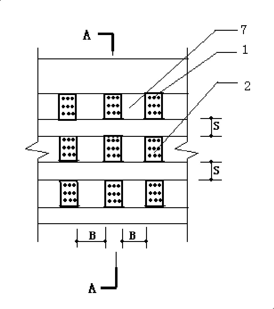
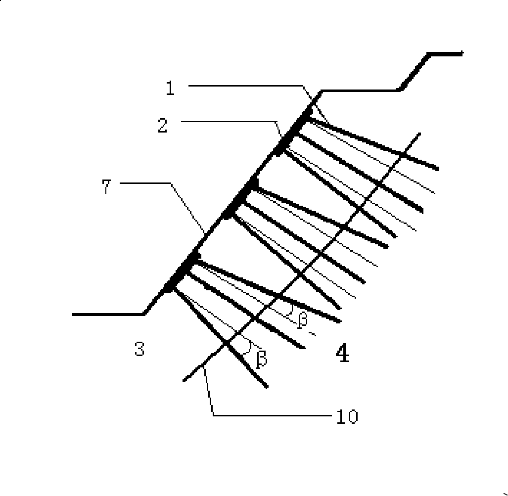
[0042] refer to figure 1 and figure 2 , the micropile anti-sliding combination structure of the present invention is arranged at 7 places on the slope surface, and it includes a plurality of top plates 2 arranged on the slope surface according to a certain row spacing S and spacing B, and the micro piles 1 fixed on each top plate 2 pass through The sliding body 3 and the sliding surface 10 are anchored in the bedrock 4 . Through the pile group effect formed by the anti-sliding micro piles arranged in rows and columns, the shear strength of the rock mass is improved, so that the entire unstable rock and soil mass becomes a whole without slipping.

Embodiment 2

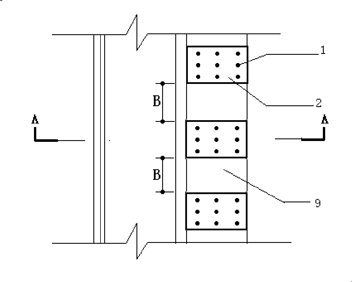
[0044] refer to image 3 , Figure 4 and Figure 5 , Figure 6 , the micro pile anti-sliding composite pile structure of the present invention is arranged at the toe platform 9 and the mid-slope platform 8, and it includes a plurality of top plates 2 arranged at a certain interval B at the toe platform 9 and the mid-slope platform 8, The micro-pile 1 fixed on each top plate 2 passes through the sliding body 3 and the sliding surface 10 and is anchored in the bedrock 4 . The pile group effect formed by the micro-pile anti-sliding composite structure arranged in rows and columns improves the shear strength of the rock mass, making the entire unstable rock and soil mass a whole without slipping.

[0045] On-site construction can usually be carried out in the following steps:

[0046] (1) construction preparation, prepare steel member 6;

[0047] (2) Level the slope or platform surface, arrange points, and drill holes;

[0048] (3) Drill the anchor hole to the design depth, ...


PUM


Abstract

The invention discloses a low-cost micro-pile anti-slide composite structure and a side slope reinforcement method in the supporting and retaining reinforcement field of deuterogene soil side slope. The micro-pile anti-slide composite structure is used for fixing the slip mass on a bedrock and comprises at least one group of micro-pile assembly which penetrates the slip mass and anchors on the bedrock; wherein, each micro-pile assembly comprises at least two micro-piles and a crest slab corresponding to the micro-pile; the crest slab is arranged on the slip mass and is fixedly connected with the micro-pile. The side slope reinforcement method includes a step of anchoring the micro-pile on the bedrock and a step of fixedly connecting the crest slab with the micro-pile; the micro-pile adopts a bored pile and the crest slab adopts a cast-in-place reinforced concrete member. The effect of pile group produced by micro-pile assembly arranged in rows and in column raises the slip resistance of rock and soil mass, which renders the unstable rock and soil mass to keep stable and prevents the rock and soil mass from sliding and damaging. The invention is mainly used for supporting and retaining reinforcement structure of unstable rock and soil side slope with medium altitude.

Description

technical field [0001] The invention relates to the stability of slopes or slopes, in particular to a retaining reinforcement structure for unstable medium-height rock-soil slopes. Background technique [0002] Medium-height rock and soil slopes refer to rock slopes with a height of less than 30m or soil slopes with a height of less than 20m. This kind of slope is damaged by sliding, and when the sliding mass slides along the sliding surface relative to the bedrock, it will also Cause larger engineering slope disasters. At present, anti-slide piles, prestressed anchor cable anti-slide piles, and anti-slide retaining walls are usually used to reinforce such slopes. Engineering practice shows that these structures have the disadvantages of large engineering volume and long construction period. and high cost. Contents of the invention [0003] In order to overcome the disadvantage of high cost of retaining reinforcement structures for existing medium-height rock-soil slopes...

Claims


Application Information

Patent Timeline
IPC IPC(8): E02D17/20E02D5/22
CPCY02A10/23
Inventor 蒋楚生周德培甘平
Owner CHINA RAILWAY ERYUAN ENG GRP CO LTD
Learn More