
Full reflection projection optical system

A technology of projection optical system and total reflection, applied in the field of projection optical system

Active Publication Date: 2010-12-22
SHANGHAI MICRO ELECTRONICS EQUIP (GRP) CO LTD
View PDF6 Cites 0 Cited by
  • Summary
  • Abstract
  • Description
  • Claims
  • Application Information

AI Technical Summary

Problems solved by technology

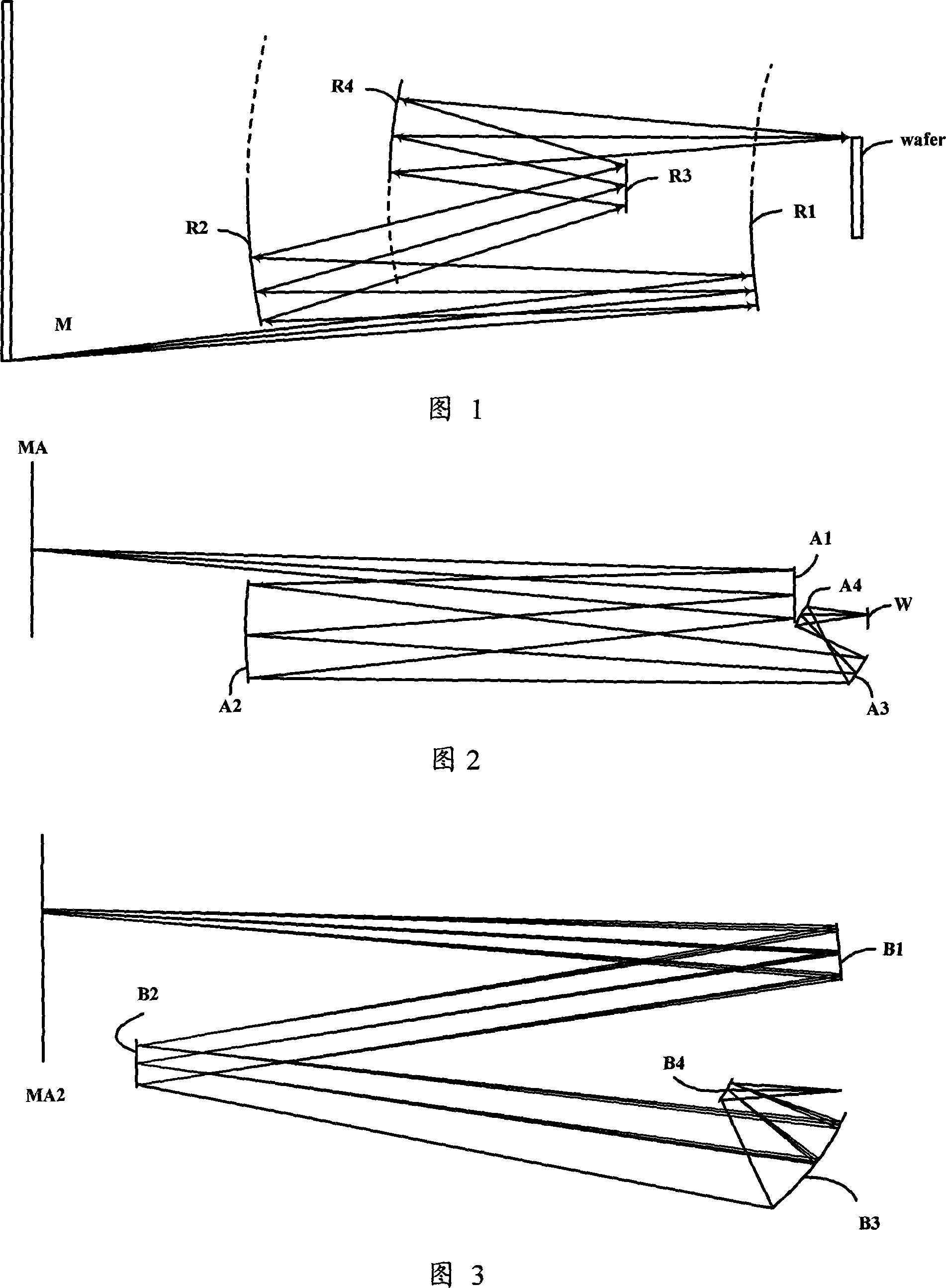
Its disadvantages are: the working distance of the image square of the two schemes is very short, and the distance between A1 and A4 is too close (such as Figure 2), which is not conducive to mechanical installation

Method used


Image

  • Full reflection projection optical system
  • Full reflection projection optical system
  • Full reflection projection optical system

Examples


Embodiment Construction

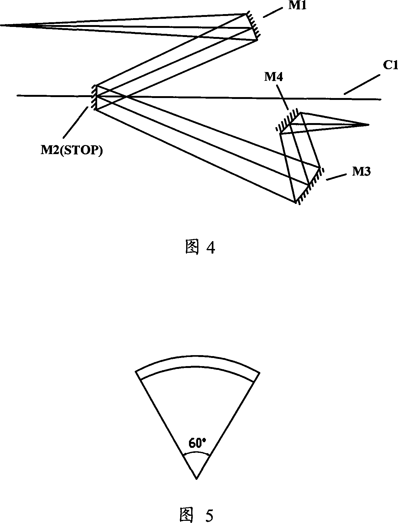
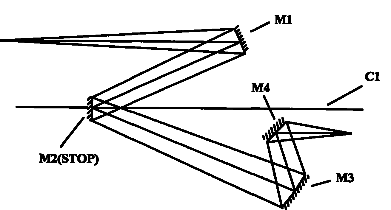
[0023] The invention provides a full reflection projection optical system, such as Figure 4 It is shown that the projection optical system is a four -picked mirror -based projector structure. The main light line and the main light of the square are parallel to the optical axis.The system consists of a mirror group, which includes the first to fourth reflective mirror M1-M4 passed by the light after the object surface.Pore diameter STOP is located on the second reflector M2, about the optical axis C1 rotating symmetry.The third reflective m3 and the fourth reflector M4 are located below the optical axis C1. After the light passes through the third reflector M3, it reaches the fourth reflector M4.The location is located below the optical axis C1.This type of full reflection projection optical system is an inverted image system with an imaging capacity between 1 / 3 and 1 / 4.

[0024] Among them, the first and fourth reflectors M1 and M4 have negative refraction capabilities, and the th...


PUM

PropertyMeasurementUnit
widthaaaaaaaaaa

Abstract

The invention provides a full reflection projection optical system which utilizes an imaging beam to project an image in an object plane of a field lens into an image plane of the field lens. The system includes a first to a fourth reflectors behind the object plane and passes through by the imaging beam in sequence; wherein, the four-side reflectors form a double telecentric projection field lens structure, namely, an aperture diaphragm is arranged on the second reflector and is rotatablely symmetrical relative to an optical shaft. The second reflector is arranged in the location of the focus of the first reflector and the third and the fourth reflectors form the image of the aperture diaphragm on an infinitely far location on the image direction. Therefore, the main beams of the object part and the main beams of the image part of the invention are parallel to the optical shaft, thus being beneficial to reducing aberrance and enlarging visual field; and the system structure is reasonable.

Description

Technical field [0001] The invention involves a projection optical system, which specializes in a full reflection projection optical system for semiconductor lithography and photographic version. Background technique [0002] With the development of projection optical technology, the performance of projection optical systems has gradually improved, and it can be applied to various fields such as integrated circuit manufacturing.The projection optical technology has been successfully applied to the field of sub -micron resolution integration circuit manufacturing.In semiconductor packaging technology, projection optical technology can be used to require lower resolution (such as a few microns), larger coke depth, higher yield, gold convex block / tin convex block, silicon wafer -level chip scale packaging (WLCSP) technology (WLCSP) technologyFields. [0003] With the continuous decrease in the characteristics of the semiconductor chip, in order to obtain a more fine structure, the w...

Claims


Application Information

Patent Timeline
Patent Type & Authority Patents(China)
IPC IPC(8): G02B17/06G03F7/20
Inventor 朱立荣储兆祥
Owner SHANGHAI MICRO ELECTRONICS EQUIP (GRP) CO LTD
Learn More