Radiation design method in PCB design

A design method and heat loss technology, applied in computing, cooling/ventilation/heating transformation, special data processing applications, etc., can solve problems such as hardware circuit instability, volume structure limitation, damage, etc., to maintain stable and good work. Heat dissipation, improved design effect

Inactive Publication Date: 2008-07-16
昆山杰得微电子有限公司
View PDF0 Cites 16 Cited by
  • Summary
  • Abstract
  • Description
  • Claims
  • Application Information

AI Technical Summary

Problems solved by technology

Especially in portable electronic products, due to the limitation of the volume and structure of electronic products, the traditional method of using heat sinks and cooling fans cannot be realized in products.
On the other hand, due to the development of IC design and the improvement of consumer requirements, the main frequency of the CPU in portable devices is getting higher and higher, and the power requirements are also getting higher and higher, which leads to heat dissipation and becomes a constraint on the development of portable products. A bottleneck, to a certain extent, limits the development of portable products
At the same time, if the heat dissipation problem is not handled properly, it may cause instability or damage to the hardware circuit on the entire board.

Method used


Image

  • Radiation design method in PCB design
  • Radiation design method in PCB design
  • Radiation design method in PCB design

Examples


Embodiment Construction

[0011] The method of the present invention will be described in further detail below in conjunction with the accompanying drawings and specific embodiments.

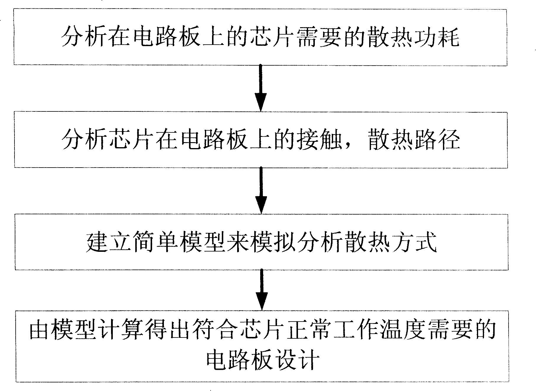
[0012] Such as figure 1 Shown, the inventive method mainly is made up of following aspects:

[0013] A. Analyze a PCB design that will generate a lot of heat loss components; determine the difference between the normal operating temperature of the chip on the PCB and the maximum limit temperature of the chip, and the power consumption of the heat loss required by the chip on the PCB;

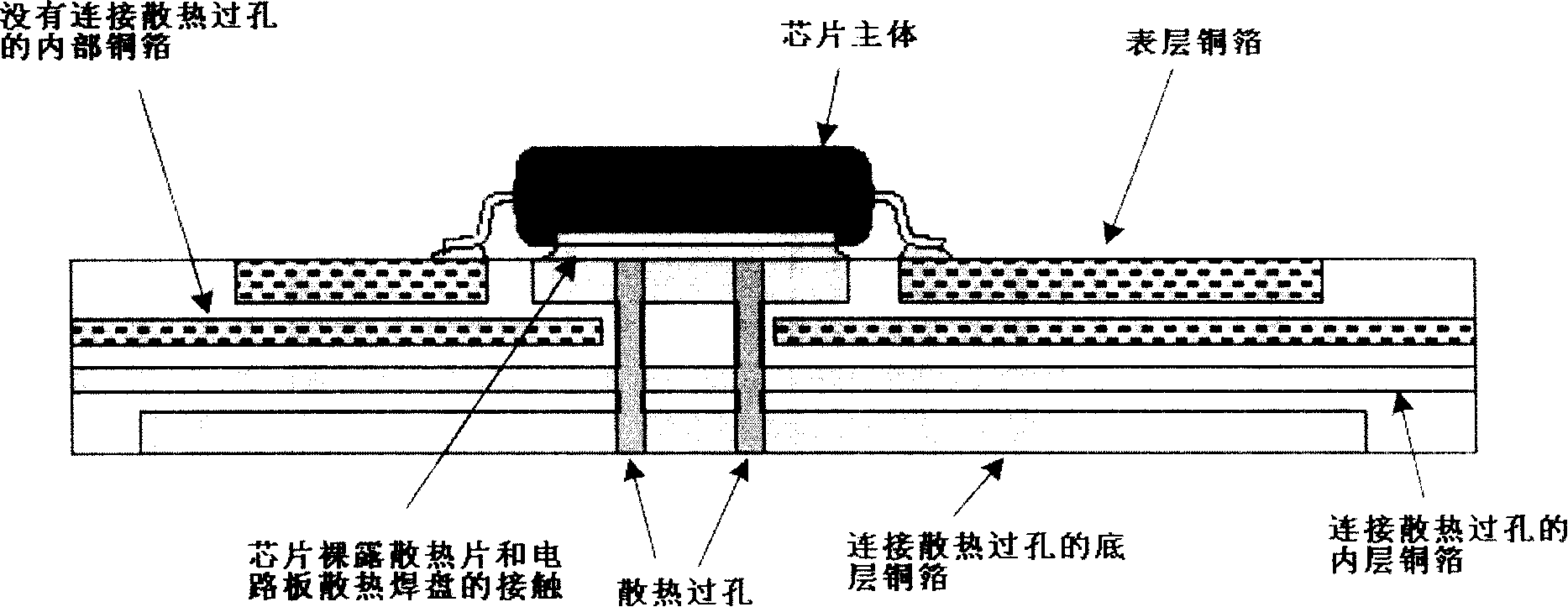
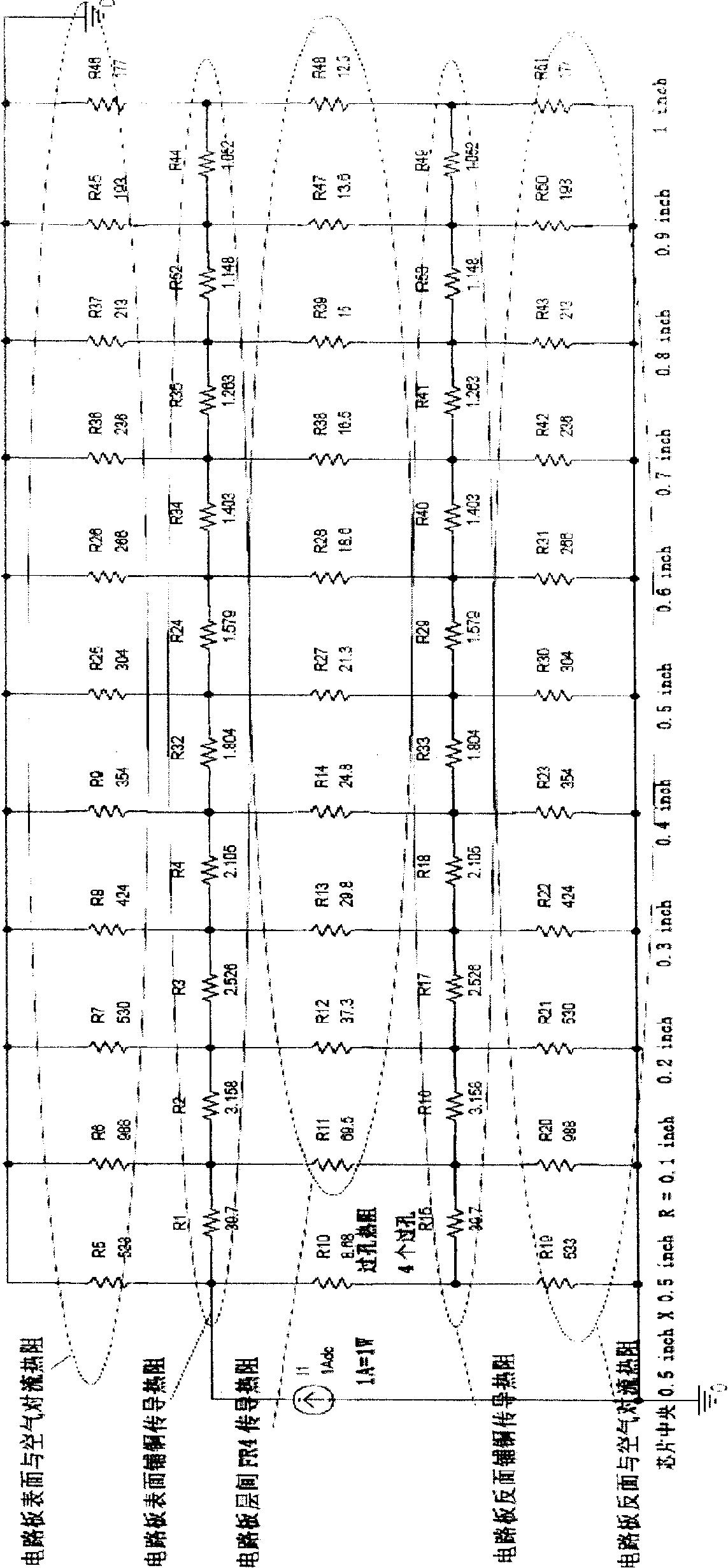
[0014] B. Analyze the soldering contact mode between these components and the PCB, as well as the laminated structure and manufacturing materials of the PCB, and the various thermal conduction methods caused by these factors, and establish a simple model based on the above to simulate the heat dissipation of the PCB;

[0015] C. Design the best heat conduction method on the PCB according to the heat dissipation model, so that the chip can...


PUM


Abstract

The invention discloses a thermal design method in the PCB design, which comprises the following steps: step 1, analyzing and determining elements generating much heat dissipation in the PCB design and the encapsulation pattern selection of the elements; determining the difference between a chip normal working temperature of the PCB and a chip maximum limiting temperature and the power consumption of the heat dissipation required by the chip on the PCB; step 2, analyzing the welding contact mode between the elements, the laminated structure and material of the PCB and corresponding heat dissipation modes; step 3, establishing a model to simulate the PCB heat dissipation and analyzing the heat dissipation modes; step4, designing the copper coil laying, the technological requirements and the laminated construction of the PCB according to model computing results, and enabling the chip to keep the normal working temperature when working on the PCB. The invention improves the design of the PCB through establishing the simple model, thereby enabling the heat dissipated by the elements to evenly reach the surface of the PCB as soon as possible, and enabling the PCB to have good heat dissipation and work stably without an external radiator.

Description

technical field [0001] The invention relates to the field of PCB (printed circuit board) design, in particular to a heat dissipation design method in PCB design, which can be applied to PCB design in hardware circuits. Background technique [0002] Under normal conditions, heat transfer includes three ways: conduction, convection and radiation. Conduction refers to the transfer of heat between objects in direct contact from the side with higher temperature to the side with lower temperature. Convection is the transfer of heat by means of fluid flow, while radiation does not need any medium, and the heating element releases heat directly to the surrounding space. In the traditional heat dissipation design, heat dissipation measures include radiators and fans, or both. The heat sink conducts the heat from the chip to the heat sink through the close contact with the chip surface. The heat sink is usually a good conductor of heat with many blades. Its fully expanded surface gre...

Claims


Application Information

Patent Timeline
Patent Type & Authority Applications(China)
IPC IPC(8): G06F17/50H05K7/20
Inventor 欧阳合潘杰黄娟王新成杨海顾群楠刘刚周逢华徐晖
Owner 昆山杰得微电子有限公司
Why Eureka
Try Eureka