High-strength novel hollow insulation composite pipe

A composite tube, high-strength technology, applied in the direction of insulators, electrical components, circuits, etc., can solve complex, safety-affecting, outer tube cracking and other problems

Inactive Publication Date: 2008-07-16
李伯明
View PDF0 Cites 10 Cited by
  • Summary
  • Abstract
  • Description
  • Claims
  • Application Information

AI Technical Summary

Problems solved by technology

At present, in order to simplify the manufacturing process and reduce the cost, the outer tube is drawn and formed. However, after the insulating composite tube made by this method is used for a certain period of time, the outer tube is prone to cracking due to the inner tube being expanded by moisture, heat and cold, which affects the use. security
At present, in order to solve this problem, the outer tube is solidified by winding the glass fiber filaments in the helical direction together with the glass fiber filaments in the pulling direction, but the inner tube needs to be rotated during manufacture, which is difficult and complicated to manufacture.

Method used


Image

  • High-strength novel hollow insulation composite pipe
  • High-strength novel hollow insulation composite pipe

Examples


Embodiment 1

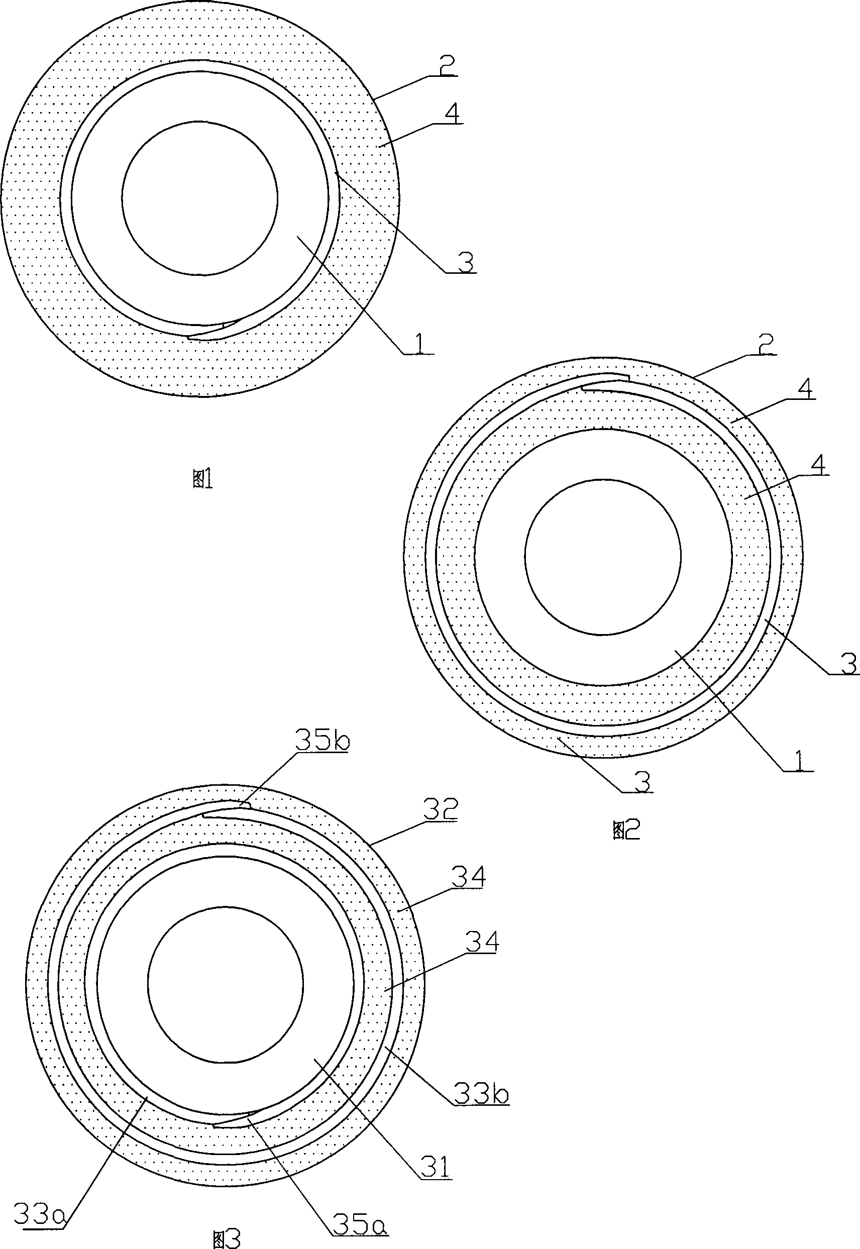
[0010] Refer to accompanying drawing 1. The present invention comprises an inner pipe 1 and an outer pipe 2 bonded with the inner pipe, the outer pipe is provided with a reinforced bonding layer 3 wrapped around the composite pipe by glass fiber cloth, and the reinforced bonding layer is combined with multiple impregnated The glass fiber strands 4 of resin solidify into the outer tube 2 .

[0011] In this embodiment, the bonding layer is one layer, located on the inner wall surface of the outer tube.

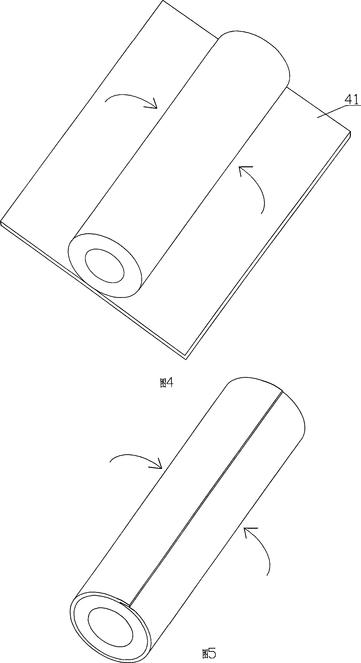
[0012] The inner tube can be made of tissue paper soaked in zinc chloride, wound in multiple layers and treated after heating, and the outer tube can be formed by drawing glass fiber yarn 4 and glass fiber cloth at one time. The direction of glass fiber yarn 4 is the same as The axes of the inner tubes are consistent. In practice, the glass fiber density of the glass fiber cloth oriented in the axial direction of the composite pipe can be greater than the density of glass fibe...

Embodiment 2

[0015] Refer to accompanying drawing 2. This embodiment is basically the same as Embodiment 1, except that the reinforcing bonding layer is in the outer tube wall.

[0016] In FIG. 2 , the reference numerals are the same as those in FIG. 1 and have the same meanings.

Embodiment 3

[0018] Refer to accompanying drawing 3. The present invention comprises an inner pipe 31 and an outer pipe 32 bonded with the inner pipe, the outer pipe is provided with a reinforced bonding layer wrapped by glass fiber cloth along the circumference of the composite pipe, and the reinforced bonding layer is combined with multiple strands of impregnated resin The glass fiber filaments 34 solidify into the outer tube 32.

[0019] In this embodiment, there are 2 reinforced bonding layers, respectively denoted by 33a and 33b, and the reinforced bonding layers are located on the inner wall surface of the outer tube and in the outer tube wall. In addition, according to the different wall thicknesses of the outer tube, one or more reinforced bonding layers may be added in the outer tube.

[0020] In practice, the seams of the reinforced bonding layers of adjacent layers are preferably staggered, which can further enhance thermal expansion and contraction resistance and torsion resis...


PUM


Abstract

The invention provides a high strength novel hollow insulation composite pipe, comprising an inner pipe and an outer pipe bonded with the inner pipe, wherein the outer pipe is provided with a strengthened bonding layer formed by the glass fiber cloth or glass fiber felt enclosing along the circumference of the composite pipe; the strengthened bonding layer and the glass fiber threads of multistrand impregnating resins are solidified into the outer pipe; when the invention is manufactured, the strengthened bonding layer can be formed on the outer pipe without turning the inner pipe, which is more convenient for manufacturing; moreover, fibers in the glass fiber cloth and the glass fiber felt are staggered, thereby the manufactured outer pipe has better capability of resisting the thermal expansion and cold contraction of the inner pipe when the inner pipe is moistened and the torsional resistance of the hollow insulation composite pipe gets better.

Description

technical field [0001] The invention relates to a hollow insulating composite pipe. Background technique [0002] An insulating composite tube of a high-voltage fuse in the field of high-voltage electrical appliances is composed of an inner tube and an outer tube bonded to the inner tube. The inner tube is a tissue paper tube soaked in zinc chloride for arc suppression. Its outer tube is made of glass fiber filaments and resin compounded and cured, which plays the role of insulating and protecting the inner tube. At present, in order to simplify the manufacturing process and reduce the cost, the outer tube is drawn and formed. However, after the insulating composite tube made by this method is used for a certain period of time, the outer tube is prone to cracking due to the inner tube being expanded by moisture, heat and cold, which affects the use. security. At present, in order to solve this problem, the outer tube is solidified by winding the glass fiber filaments in t...

Claims


Application Information

Patent Timeline
Patent Type & Authority Applications(China)
IPC IPC(8): H01B17/58H01H85/042
Inventor 李伯明
Owner 李伯明
Why Eureka
Try Eureka