Method for liquefying a hydrocarbon-rich flow

A hydrocarbon flow and mixed refrigerant technology, applied in liquefaction, refrigeration, liquefaction, solidification, etc., can solve the problems of high cost and high equipment, and achieve the effect of low unit energy consumption and compact equipment or process

Inactive Publication Date: 2008-07-16
LINDE AG
View PDF2 Cites 9 Cited by
  • Summary
  • Abstract
  • Description
  • Claims
  • Application Information

AI Technical Summary

Problems solved by technology

However, the use of low-pressure evaporated refrigerant necessaril

Method used


Image

  • Method for liquefying a hydrocarbon-rich flow

Examples


Embodiment Construction

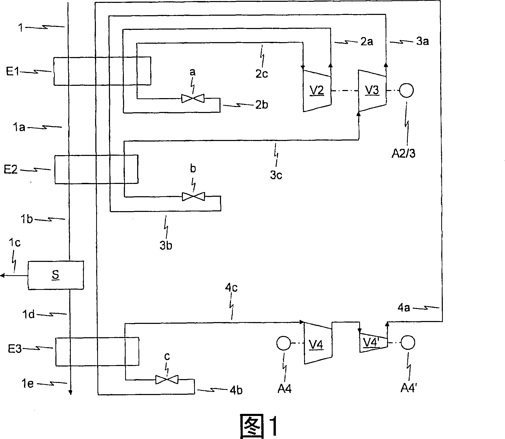
[0025] The hydrocarbon-rich stream to be liquefied is cooled in heat exchanger E1 against the vaporized mixed refrigerant stream 2b of the first mixture cycle 2a-2c. Next, the hydrocarbon-rich stream is sent through line 1a to heat exchanger E2 and in this heat exchanger is further cooled against the evaporated mixed refrigerant stream 3b of the second mixture cycle 3a-3c.

[0026] At the outlet of heat exchanger E2, the temperature of the cooled hydrocarbon-rich stream is -30°C to -70°C, preferably -40°C to -60°C. It is now conveyed via line 1b to a separation unit S, shown only as a black box.

[0027] In this separation unit S the above-mentioned C 3+ Separation, in which the components separated from the hydrocarbon-rich stream to be liquefied are discharged from the separation unit S through line 1c.

[0028] The hydrocarbon-rich stream to be liquefied is then sent via line 1d to the third heat exchanger E3 and is liquefied and subcooled in this heat exchanger against t...


PUM


Abstract

The invention relates to a method for liquefying a hydrocarbon-rich stream, in particular a natural gas stream, wherein the liquefaction of the hydrocarbon-rich stream is carried out against a mixed refrigerant cycle cascade consisting of three mixed refrigerant cycles. According to the invention, the first and second mixed refrigerant cycles (2a-2b, 3a-3b) are used for precooling, and the third mixed refrigerant cycle (4a-4b) is used for liquefaction and subcooling of the hydrocarbon-rich stream. Here, the first and/or second mixed refrigerant cycle (2a-2b, 3a-3b) is preferably designed as a single-stage mixed refrigerant cycle, while the third mixed refrigerant cycle (4a-4b) is preferably designed as It is a two-stage mixed refrigerant cycle.

Description

technical field [0001] The invention relates to a method for liquefying a hydrocarbon-rich stream, in particular a natural gas stream, wherein the liquefaction of the hydrocarbon-rich stream is carried out against a mixed refrigerant cycle cascade consisting of three mixed refrigerant cycles. [0002] The term "first mixed refrigerant cycle" below should always be understood to mean a carbon dioxide refrigerant cycle. Background technique [0003] A process of the stated type for liquefying a hydrocarbon-rich stream is known from German laid-open document 197 16 415 . By reference to this German laid-open document 197 16 415, the disclosure content of which is incorporated in the disclosure content of the present patent application. [0004] The natural gas liquefaction plant is designed either as a so-called LNG baseload plant - that is, a natural gas liquefaction plant that uses natural gas as the primary energy supply - or as a so-called peak shaving plant - that is, a n...

Claims


Application Information

Patent Timeline
IPC IPC(8): F25J1/02
CPCF25J1/0022F25J1/0052F25J1/0217F25J1/0218F25J1/0282F25J1/0283F25J1/0284F25J1/029F25J1/0292F25J1/0295F25J2220/64
Inventor H·鲍尔R·扎佩尔
Owner LINDE AG
Why Eureka
Try Eureka