Wheel boss motor power wheel

An in-wheel motor and wheel technology, applied in electric vehicles, electric power devices, motors, etc., can solve the problem that the volume of high-power motors cannot be directly installed on the vehicle chassis, hindering the rapid development, progress and popularization of electric vehicles, low-power Insufficient output torque of the motor, etc., to achieve the effect of facilitating the mechanization of the assembly line, saving on-board power, and simple processing and assembly methods

Inactive Publication Date: 2008-07-23
任海
View PDF0 Cites 25 Cited by
  • Summary
  • Abstract
  • Description
  • Claims
  • Application Information

AI Technical Summary

Problems solved by technology

Obviously, the large motor plus the mechanical transmission system such as mechanical gearbox, coupling, transmission shaft, etc., is both large and heavy, which not only takes up valuable space in the car, but also wastes a lot of valuable on-board electric energy due to mechanical wear and tear.
The output torque of low-power motors is obviously not enough. High-power motors are not only limited by their size and cannot be directly installed on the chassis of the vehicle, but also limited by the energy of the vehicle's battery.
This is one of the practical technical difficulties currently restricting the development of electric vehicle power systems, which has hindered the rapid development, progress and popularization of electric vehicles for a long time

Method used


Image

  • Wheel boss motor power wheel
  • Wheel boss motor power wheel
  • Wheel boss motor power wheel

Examples


Embodiment Construction

[0020] Below again in conjunction with accompanying drawing, the specific embodiment of the application of the present invention is described in further detail:

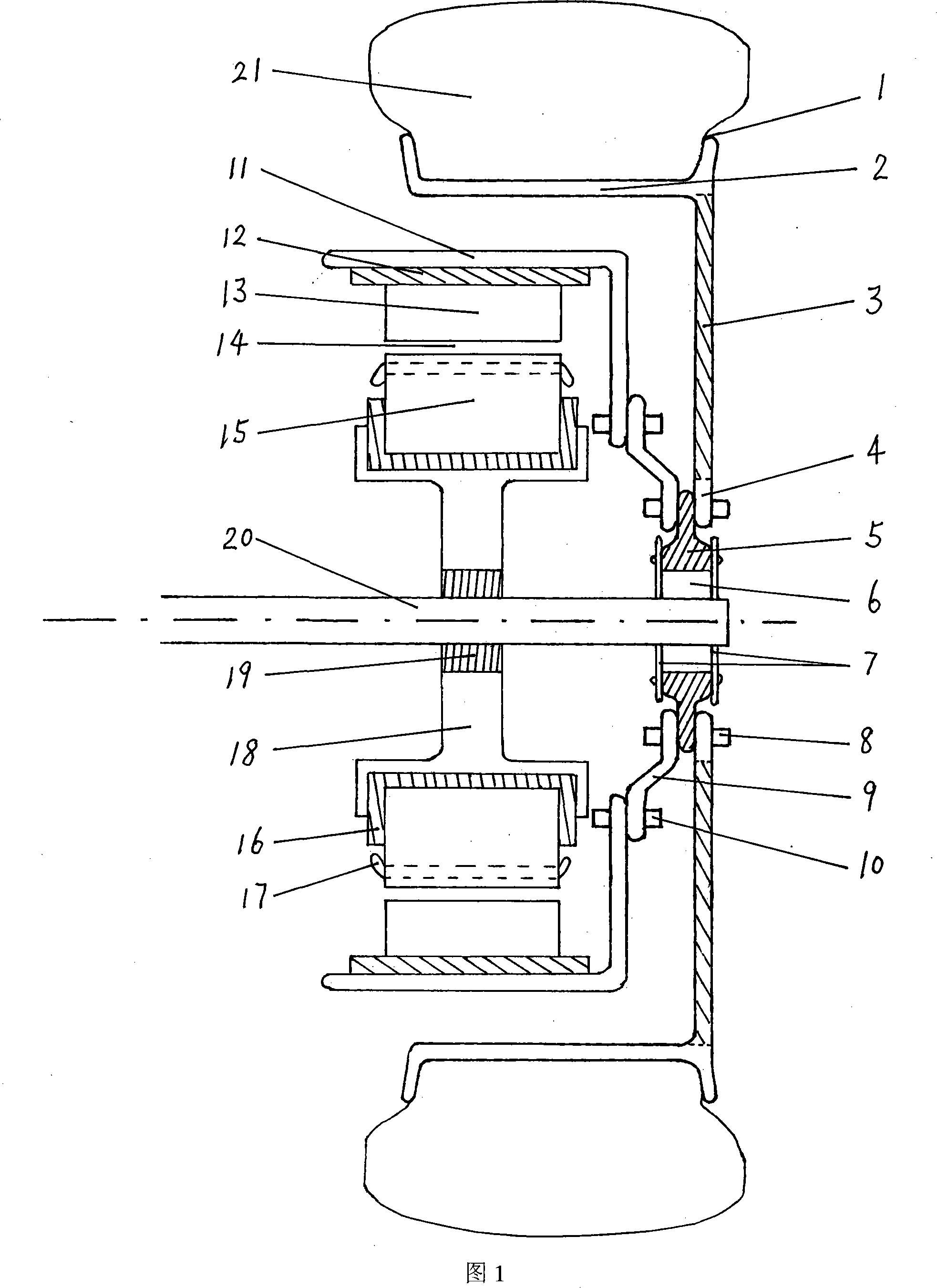
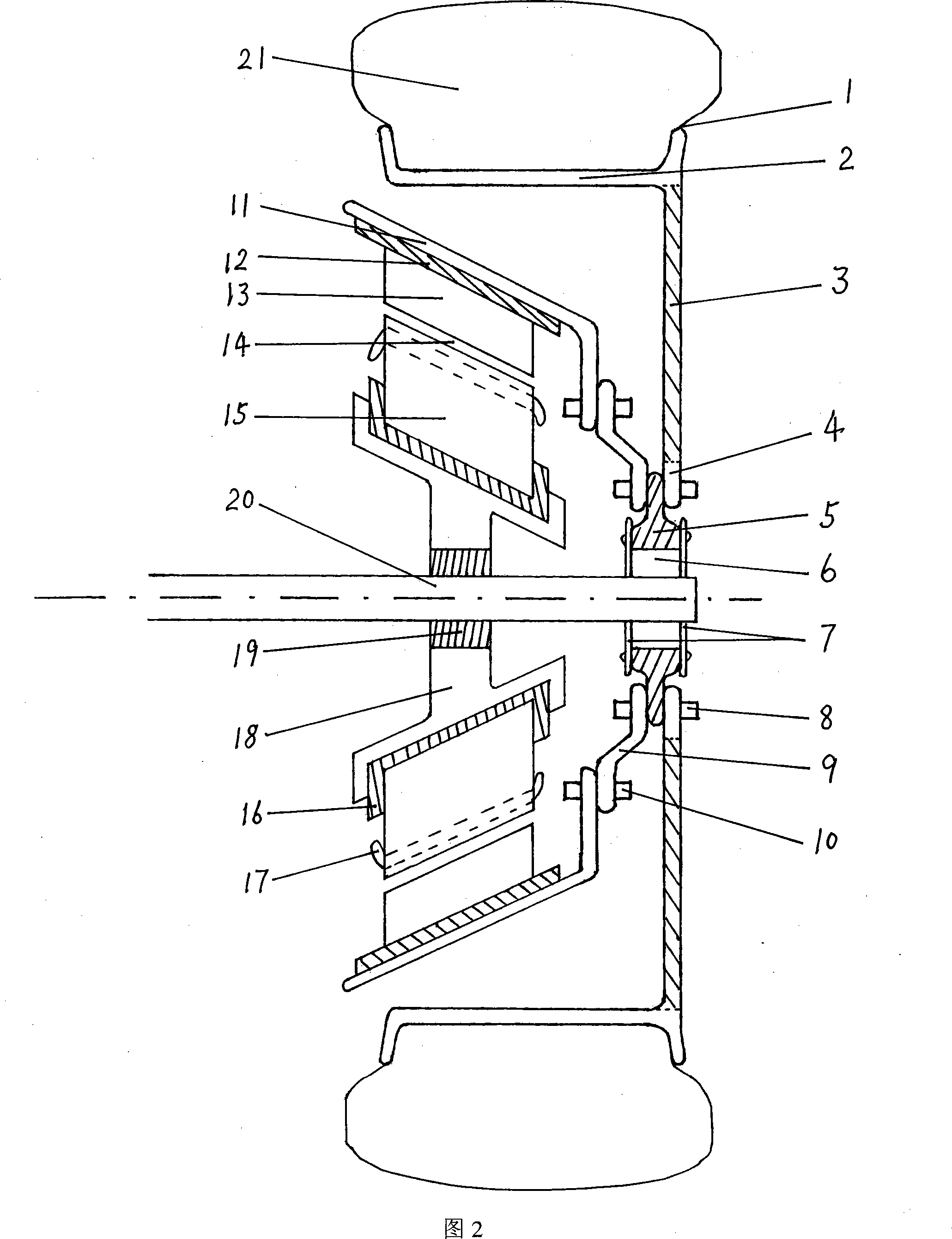
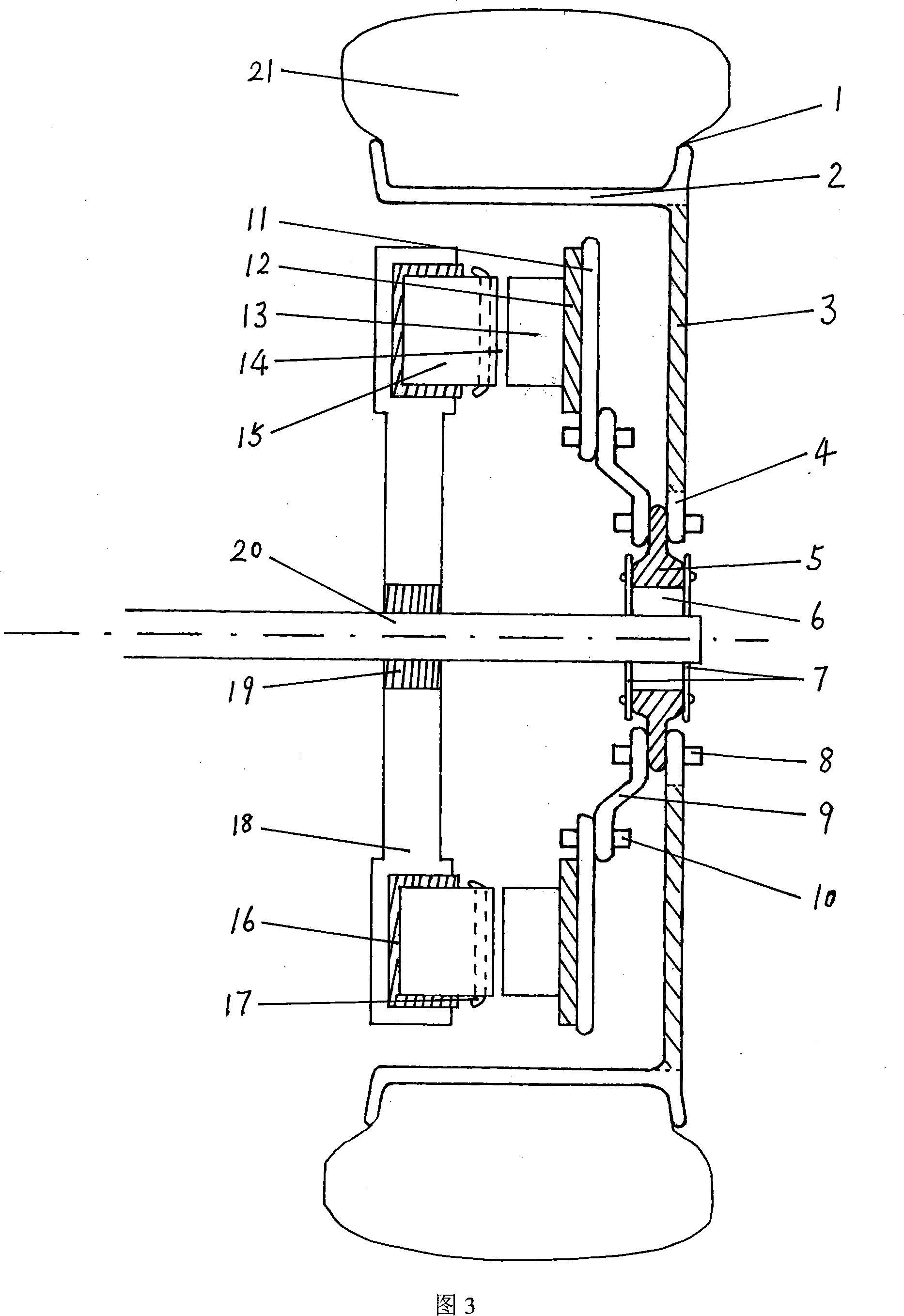
[0021] Shown in accompanying drawing 1, be an embodiment of the application of the present invention. In the power wheel shown in FIG. 1 , the three mechanical parts of the bearing support connecting plate 5 tightly sleeved outside the bearing 6 on the axle 20 , the wheel hub 4 and the motor rotor bracket 9 are connected and fastened by the hub connecting bolts 8 become a mechanical whole. The motor primary stator 15 is connected and fixed with the axle to form a mechanical whole through the motor stator fastening yoke 16, the motor stator frame 18 and the motor stator frame seat 19. Because the axle is determined to be stationary by other components (such as vehicle frame, suspension, etc.) other than the wheel, the primary stator 15 of the motor is also determined to be stationary together with the axle. When cur...


PUM


Abstract

The invention relates to a power wheel of a hub motor which comprises a wheel hub, a wheel rib, a wheel felloe of a vehicle and vehicle tyres, a vehicle shaft, a bearing and a connecting disk supported by the bearing which are arranged inside, as well as a motor primary stator, a stator frame, a frame seat, a stator-fastening yoke, a stator winding, a motor secondary rotor, a rotor-fastening yoke, a rotor frame, a motor inter-air space, a motor rotor bracket and connecting bolts which are fixedly connected on the vehicle shaft. The power wheel uses the advanced techniques of computers, frequency conversion, voltage regulation and inversion, etc. for implementing the control and the driving of the hub motor, thus outputting the torque which is large enough to satisfy the starting, grade climbing and high-speed driving requirements of electric vehicles. The integrated mechanical and electric structure design of the invention has novel conception, advanced techniques and great practicability; the invention has simple and reliable structure, low cost, convenient production and installation. The invention can conveniently form the wheel power system of the hub motor of electric vehicles so as to promote the quick development and improvement of electric vehicles.

Description

technical field [0001] The application of the present invention relates to a wheel with its own power, that is, an in-wheel motor is installed inside. The mechatronic structure of the wheel can conveniently constitute the in-wheel motor and wheel power system for electric vehicles. Background technique [0002] The existing electric vehicle wheels themselves are all without power, and all rely on the vehicle-mounted power system to drive the axle to drive the wheels to rotate and advance. The existing electric vehicle power system generally uses a high-power motor to drive the axle through a transmission system such as a mechanical gearbox, and then the axle drives the wheel to rotate forward; Directly drives the wheel hub to rotate to drive the wheel forward. Obviously, the large motor plus the mechanical transmission system such as mechanical gearbox, coupling, transmission shaft, etc., is both large and heavy, which not only takes up valuable space in the car, but also w...

Claims


Application Information

Patent Timeline
Patent Type & Authority Applications(China)
IPC IPC(8): B60K7/00B60K1/00H02K7/14
CPCY02T10/641Y02T10/64
Inventor 任海
Owner 任海
Why Eureka
Try Eureka