
Composite insulator and manufacturing method thereof

A technology of composite insulators and sheds, applied in the high-voltage field, can solve the problems of moisture on the outer insulating surface, unfavorable water droplet aggregation and rolling, partial discharge, etc. sexual effect

Inactive Publication Date: 2008-07-23
丁清
View PDF1 Cites 12 Cited by
  • Summary
  • Abstract
  • Description
  • Claims
  • Application Information

AI Technical Summary

Problems solved by technology

[0003] The inclination angle of the shed of the composite insulator of the existing umbrella structure is small, which is not conducive to the aggregation and rolling of water droplets. The insulating surface is completely exposed to the air flow. The carried moisture tends to make the outer insulating surface moist; in a rainy climate, the rain falls on the dirty shed, and the sewage will splash back to the sheath and other clean and dry insulating surfaces, which will aggravate the pollution of the composite insulator in the rain. Condition; In the climate of snowfall and freezing, the snow and ice accumulation on the upper surface of the shed are serious, and when the snow melts and ice melts, it will also affect the pollution and humidity of the composite insulator
When the composite insulator is in a poor pollution and humidity condition, it will cause pollution flashover, partial discharge, and corrosion of the outer insulating material of the composite insulator. Therefore, the pollution and humidity resistance of the existing composite insulator needs to be improved to improve the reliability

Method used


Image

  • Composite insulator and manufacturing method thereof
  • Composite insulator and manufacturing method thereof
  • Composite insulator and manufacturing method thereof

Examples


Embodiment Construction

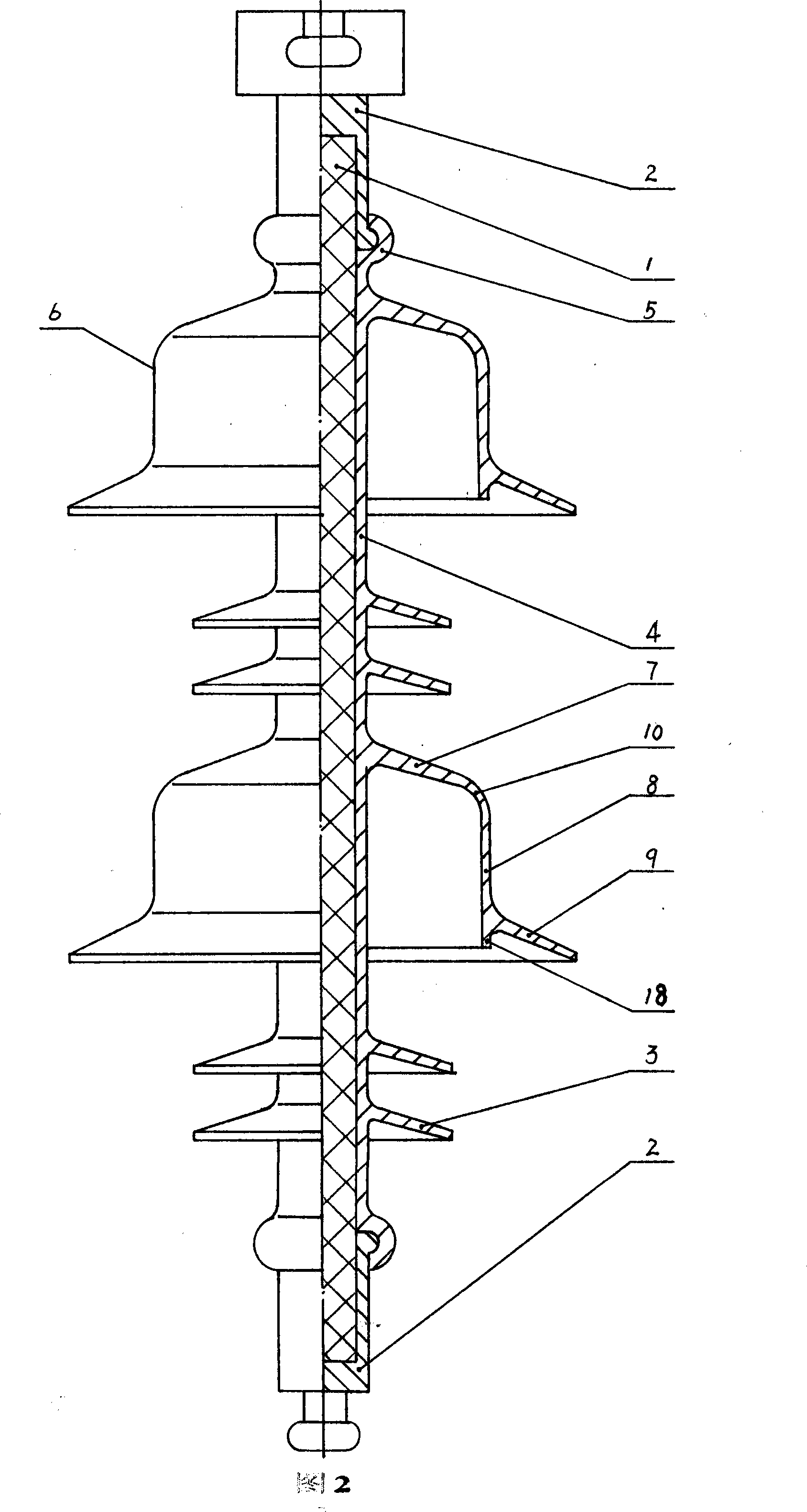
[0027] Fig. 2 is a half-sectional view of a composite insulator of the present invention. The umbrella structure of the composite insulator is composed of two shed groups connected in series under a hooded shed and 2 ordinary sheds in series. After extending outward at an inclination angle of 85° to form an upper slope, it extends downward at an inclination angle of 85° to form a vertical surface, and then extends outward at an inclination angle of 30° to form a lower slope. The flow pair of sheds forms a hat-like shed, and the upper slope and the vertical surface form a hollow-shaped shed with a height of about 50 mm. The diameter of the bottom of the flow shed.

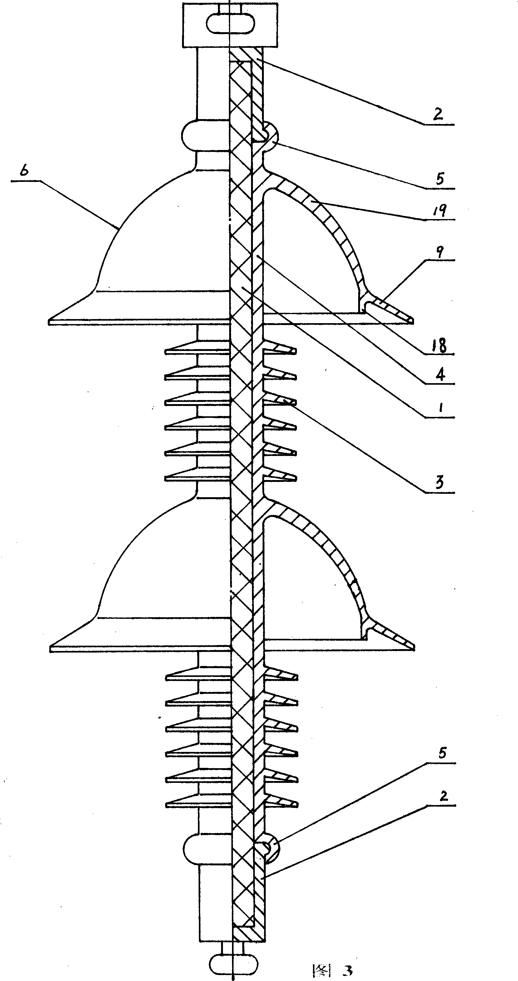
[0028] Fig. 3 is a half-sectional view of a composite insulator of the present invention. The umbrella structure of the composite insulator is composed of two shed groups connected in series under a hat-like shed and 6 ordinary sheds. The top of the hat-like shed is connected to the sheath in an arc The way exten...


PUM


Abstract

The invention discloses a composite insulator and the producing method thereof. The umbrella form of the composite insulator is composed of shed groups formed by concatenating ordinary sheds (3) under a plurality of cap type sheds (6), the cap sheds are formed by cavity type cap sheds with height over 40 millimeters and downward slant faces (9), the cavity type cap sheds of the cap type sheds (6) can keep relatively dry in humid climate to increase the pollution and moisture resisting property. The method of producing the composite insulator comprises positioning a mandrel bar provided with a connecting hardware in a mould combined by a fixed mould and a movable mould, filling silicon rubber in the mould cavity and vulcanizing, when demoulding, releasing the movable mould and the composite insulator together from the fixed mould, then detaching from the cap type sheds. Another method of producing the composite insulator of the invention comprises respectively compressing inner housings, cap type sheds, ordinary sheds and end sealing layers, enabling directionally interleaving grooves to be arranged on the inner housings and in the outer housings, covering the cap type sheds and the ordinary sheds on the inner housings by sheds penetrating technique, filling the groove with insulators with vacuum technique and then installing the connecting hardware.

Description

technical field [0001] The invention belongs to the technical field of high voltage, and in particular relates to a composite insulator installed and used vertically in a high-voltage power transmission and transformation system, in particular to a rod-shaped suspension composite insulator used in a power transmission and transformation line. The invention also relates to a method for manufacturing the composite insulator. Background technique [0002] In the book "Insulators and External Insulation of Power Transmission and Transformation Equipment" published by Tsinghua University Press in 2006 and edited by Professor Guan Zhicheng of Tsinghua University, in Chapter 2, Section 2 "Composite Insulators", the structure of existing composite insulators is discussed in detail and manufacturing methods, and summarizes the umbrella structure of existing composite insulators by means of structural illustrations and photo illustrations, and further discusses the pollution and humid...

Claims


Application Information

Patent Timeline
Patent Type & Authority Applications(China)
IPC IPC(8): H01B17/04H01B19/00
Inventor 丁清
Owner 丁清
Learn More