Cast-in-situs reinforcing wire concrete floor

A reinforced concrete floor slab and reinforced concrete technology, applied in the field of cast-in-place reinforced concrete slabs, can solve the problems of troublesome hollow tube production, high cost, and increased cost of hollow slabs

Inactive Publication Date: 2008-07-30
湖南邱则有专利战略策划有限公司
View PDF0 Cites 1 Cited by
  • Summary
  • Abstract
  • Description
  • Claims
  • Application Information

AI Technical Summary

Problems solved by technology

In this way, the production of the hollow tube is troublesome and the cost is relatively high, which undoubtedly increases the cost of the hollow floor.

Method used


Image

  • Cast-in-situs reinforcing wire concrete floor
  • Cast-in-situs reinforcing wire concrete floor
  • Cast-in-situs reinforcing wire concrete floor

Examples


Embodiment Construction

[0036] The present invention will be further described below in conjunction with the accompanying drawings and embodiments.

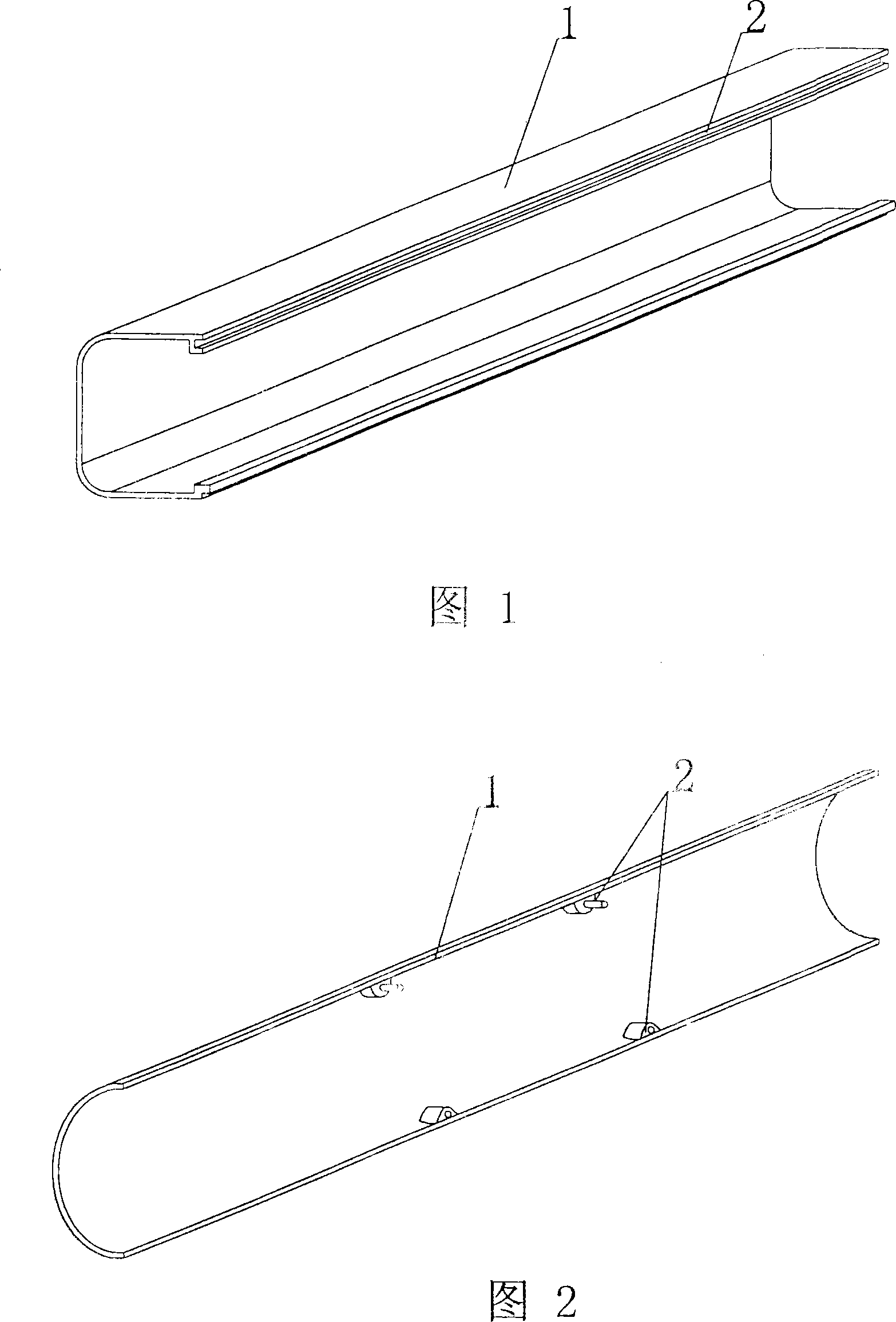
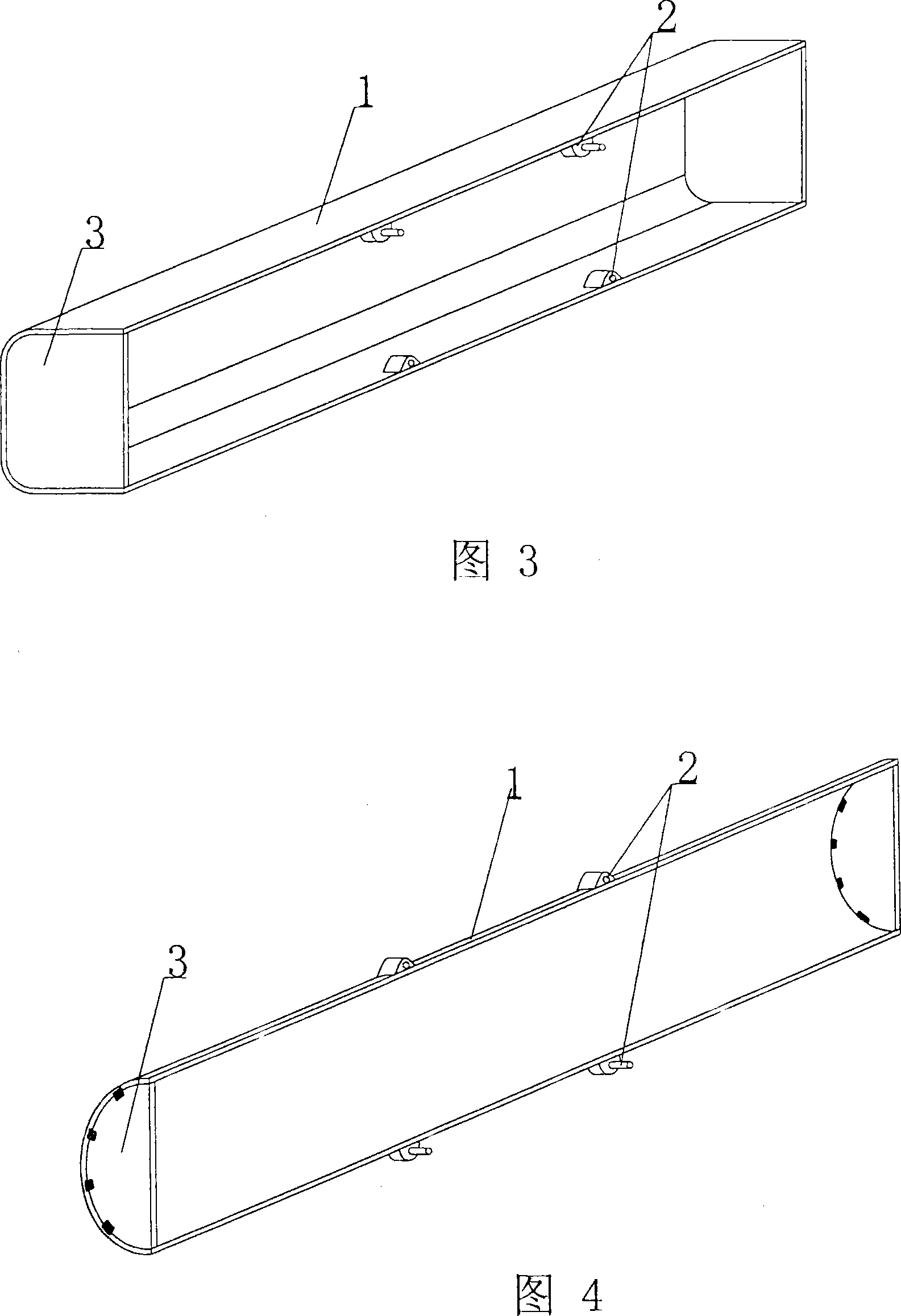
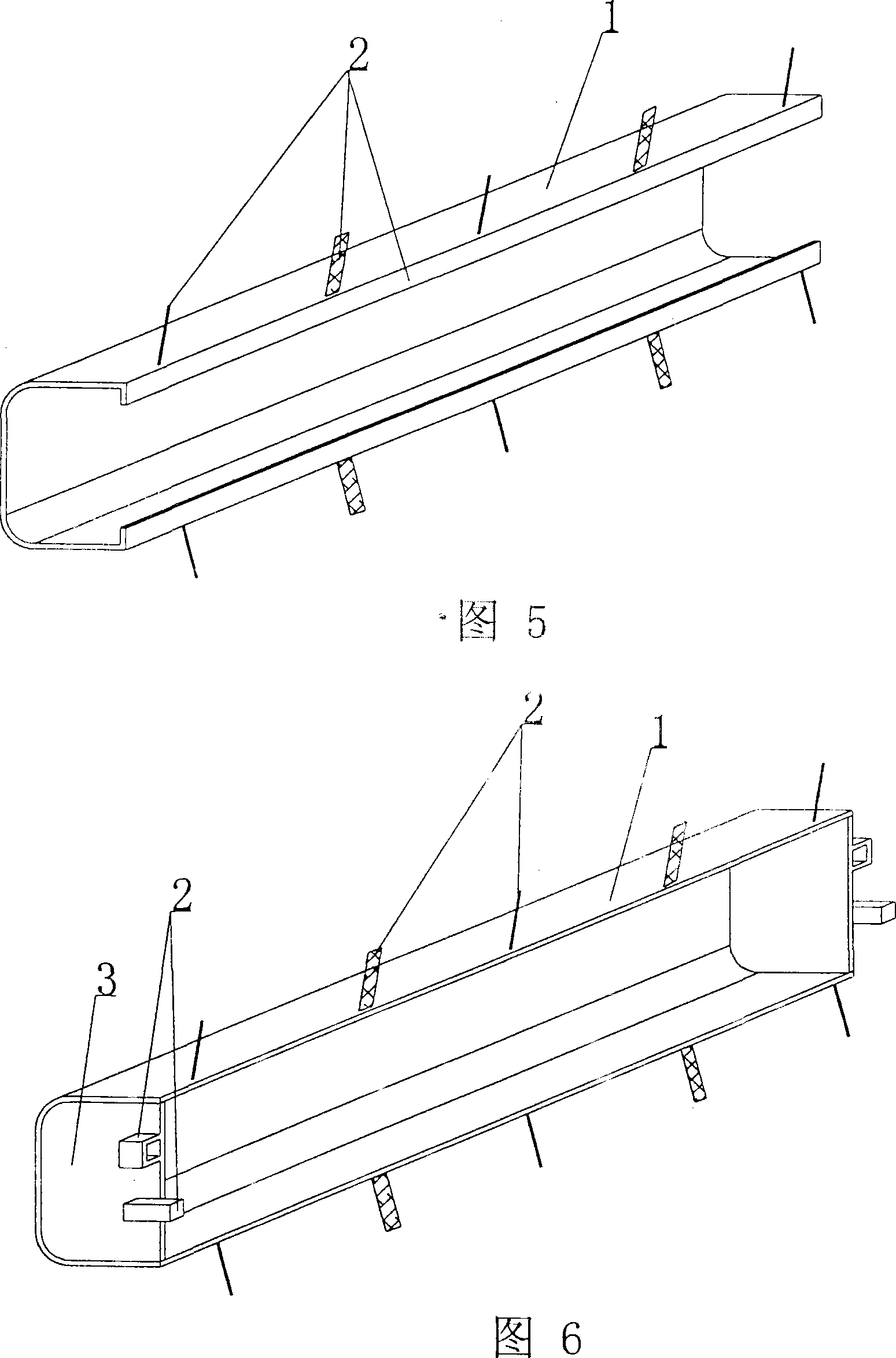
[0037] As shown in the accompanying drawings, the present invention comprises reinforced concrete and a hole-forming member, and is characterized in that the hole-forming member is an integral member composed of a combination part 1 to form a cavity, and the combination part 1 is provided with a connecting piece 2 for combination. The part 1 has a groove 9 and a stiffener 12 in the groove 9 position. In the accompanying drawings, 1 is an assembly part, and 2 is a connecting piece. In each accompanying drawing, those with the same number have the same description. As shown in Figure 1, the hole-forming member is a combination part 1 that constitutes a combined cavity-forming integral part, on which are provided joints 2 for combination, shown as a half-side square-round tubular combination part, and can also be three-pointed. Combination parts in the fo...


PUM


Abstract

The invention discloses a cast-in-situ reinforced concrete floor slab, which comprises reinforced concrete and a pore-forming component. The invention is characterized in that the pore-forming component is an integral component used for combining into a cavity for a composite component (1) which is provided with a commissural component (2) for the purpose of combination and a groove (9) which is provided with a stiffener (12), therefore, the invention is suitable for various cast-in-situ reinforced concrete hollow floor systems, roof systems, foundation slabs, walls and vierendeel bridge girders.

Description

[0001] This application is a divisional application of an invention patent application with an application date of December 22, 2002, an application number of 02158263.7, and a title of "a component for forming holes in cast-in-place reinforced concrete". (1) Technical field [0002] The invention relates to a cast-in-place reinforced concrete floor slab. (2) Background technology [0003] At present, in the prior art, the hole-forming components of the cast-in-place hollow floor slab are permanent mandrels, such as paper tubes, plastic tubes, metal bellows, and lightweight materials for mandrels. These tubular mandrels or components are mainly considered to evacuate the concrete and reduce the weight of the floor slab. For example, the patent No. ZL99249775.8 applied by the applicant is a utility model patent named "fiber-reinforced thin-walled tube for filling cast-in-place reinforced concrete". It consists of a hard thin-walled tube and plugs at both ends. The head seals...

Claims


Application Information

Patent Timeline
Patent Type & Authority Applications(China)
IPC IPC(8): E04B5/36E04B2/86E04C1/00E04G15/06E04G11/36E02D27/00
Inventor 邱则有
Owner 湖南邱则有专利战略策划有限公司
Why Eureka
Try Eureka