Liquid crystal display, method for producing liquid crystal display, and electronic apparatus

A technology of a liquid crystal display device and a manufacturing method, which are applied in the directions of static indicators, nonlinear optics, optics, etc., can solve the problems of complicated manufacturing processes and the like, and achieve the effect of high suppression effect.

Inactive Publication Date: 2008-07-30
SEIKO EPSON CORP
View PDF1 Cites 9 Cited by
  • Summary
  • Abstract
  • Description
  • Claims
  • Application Information

AI Technical Summary

Problems solved by technology

Therefore, in addition to the process of separately forming the additional insulating film, it is necessary to separately form the through-hole that penetrates only the additional insulating film, and there is a problem that the manufacturing process is complicated.

Method used


Image

  • Liquid crystal display, method for producing liquid crystal display, and electronic apparatus
  • Liquid crystal display, method for producing liquid crystal display, and electronic apparatus
  • Liquid crystal display, method for producing liquid crystal display, and electronic apparatus

Examples


no. 1 approach

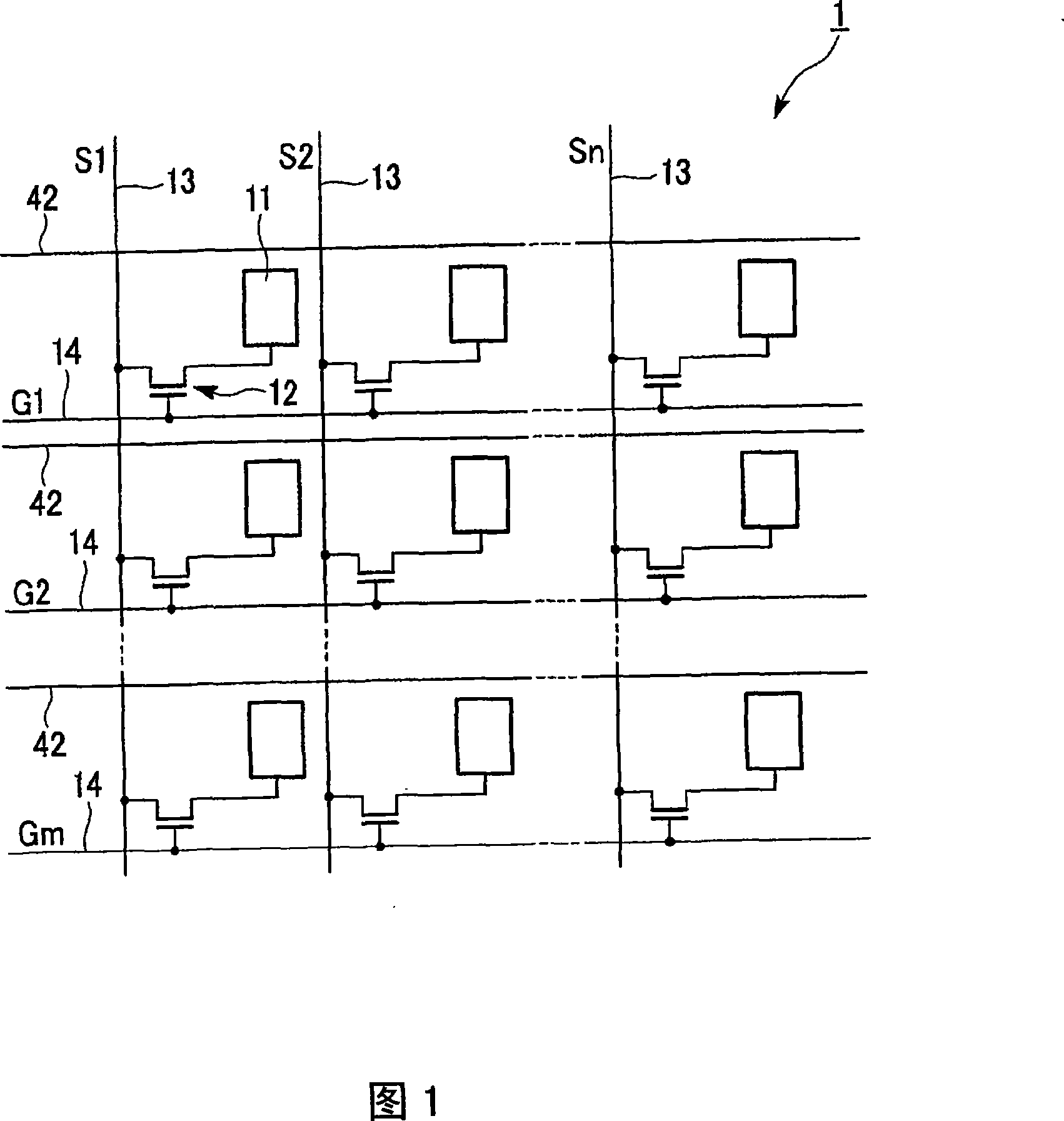
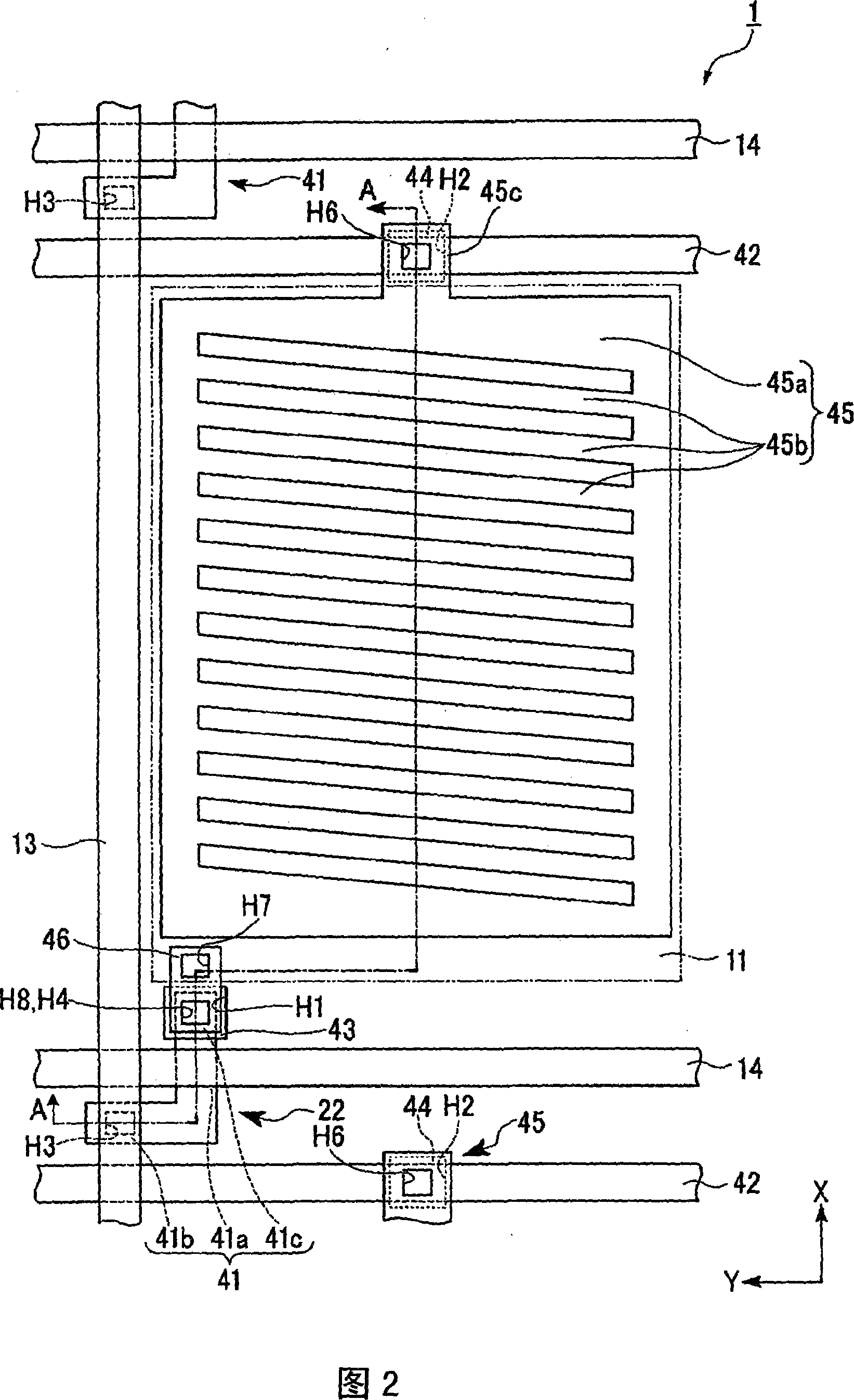
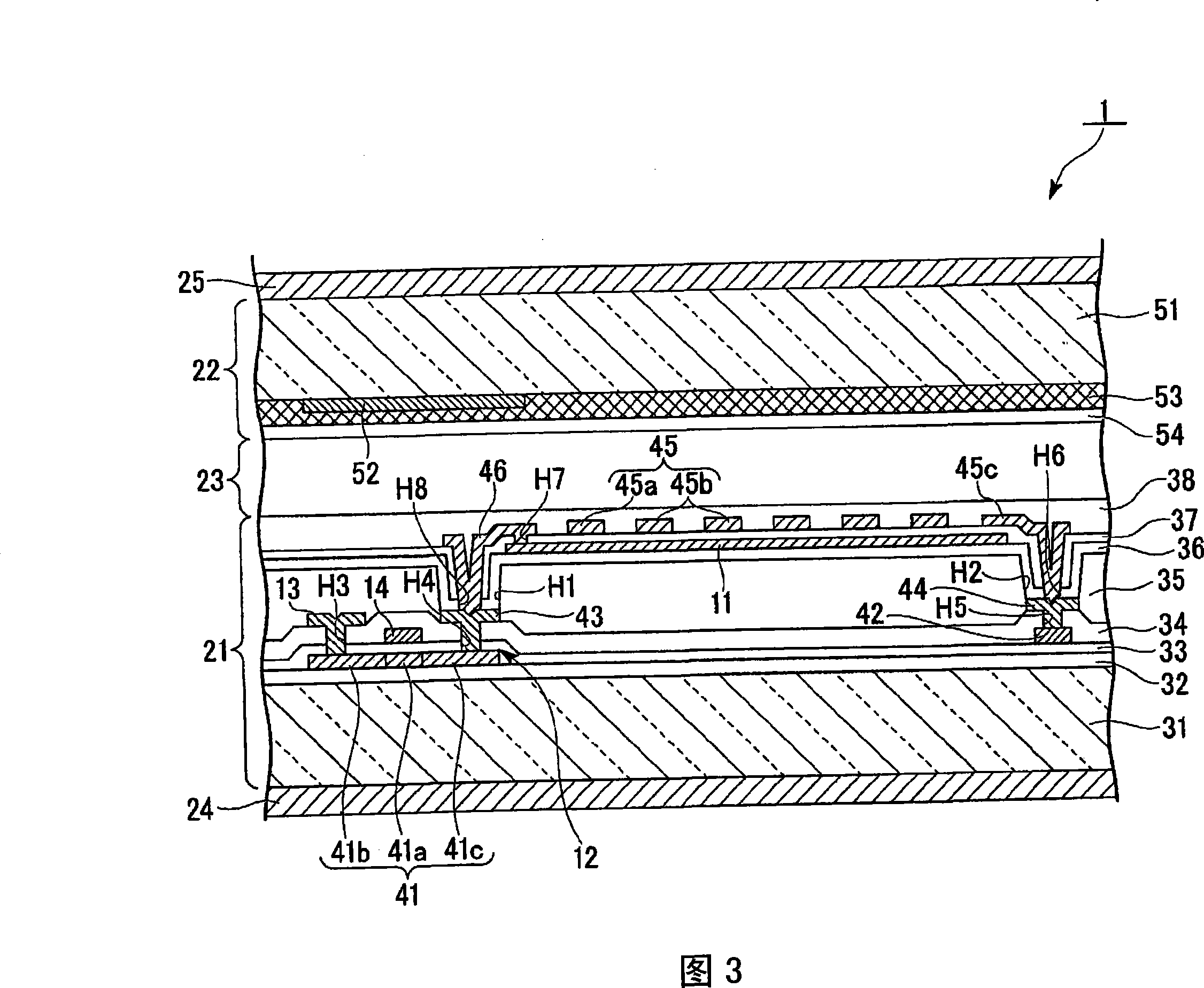
[0038] Hereinafter, a first embodiment of the liquid crystal display device of the present invention will be described with reference to the drawings. In addition, in each drawing used for the following description, since each member is set to the recognizable size, reduction ratio can be changed suitably. Here, FIG. 1 is an equivalent circuit diagram of a liquid crystal display device, FIG. 2 is a plan view showing a sub-pixel region, and FIG. 3 is a sectional view taken along the line A-A of FIG. 2 .

[0039] [Liquid crystal display device]

[0040] The liquid crystal display device 1 of the present embodiment is a transmissive color liquid crystal display device in which one pixel is constituted by three sub-pixel regions that output light of each color R (red), G (green), and B (blue). Here, a display area serving as a minimum unit constituting a display is referred to as a "sub-pixel area".

[0041] First, a schematic configuration of the liquid crystal display device 1...


PUM


Abstract

A liquid crystal display includes a pair of substrates, a liquid crystal layer being held by the pair of substrates, a first electrode and a second electrode that drive the liquid crystal layer, and a driving element that controls the driving of the first electrode, the first electrode, the second electrode, and the driving element being disposed on one of the pair of substrates. The one of the pair of substrates includes a resin film, an overlying film disposed on the resin film, the first electrode being disposed on the top surface of the overlying film, an electrode insulating film covering the first electrode, the second electrode being disposed on the top surface of the electrode insulating film, a connection electrode disposed on the electrode insulating film and connecting the first electrode to the driving element, and a connection line disposed below the overlying film and connected to the second electrode. The connection electrode is connected to the first electrode through a first through hole passing through the electrode insulating film and is connected to the driving element through a second through hole passing through the overlying film and the electrode insulating film. The second electrode is connected to the connection line through a third through hole passing through the overlying film and the electrode insulating film.

Description

technical field [0001] The present invention relates to a liquid crystal display device, a method for manufacturing the liquid crystal display device, and electronic equipment. Background technique [0002] As one means for realizing a wide viewing angle of a liquid crystal display device, a method (hereinafter referred to as a lateral electric field method) is known in which the liquid crystal layer generates an electric field in the direction of the substrate to control the orientation of liquid crystal molecules. As such a lateral electric field As the method, IPS (In-Plane Switching) method or FFS (Fringe-Field Switching) method are known (for example, refer to Patent Document 1). [0003] In a liquid crystal display device using such a transverse electric field method, a pair of electrodes for driving liquid crystal molecules, that is, a pixel electrode and a common electrode. Generally, one electrode formed under the electrode insulating film is formed on a resin fil...

Claims


Application Information

Patent Timeline
Patent Type & Authority Applications(China)
IPC IPC(8): G02F1/133G02F1/1345G02F1/1333G02F1/1362
CPCG02F1/136227G02F1/134363
Inventor 松本友孝
Owner SEIKO EPSON CORP
Why Eureka
Try Eureka