Display device

A display device and secondary display technology, which is applied to static indicators, instruments, etc., can solve the problems of increased drive signal line power, high display pattern frequency, and insufficient power consumption, so as to ensure low power and suppress image quality deterioration , the effect of less data

Active Publication Date: 2008-07-30
JAPAN DISPLAY INC
View PDF8 Cites 21 Cited by
  • Summary
  • Abstract
  • Description
  • Claims
  • Application Information

AI Technical Summary

Problems solved by technology

Even in the case of writing black data into the non-display area, voltage writing is performed at a ratio of one horizontal period among multiple horizontal periods, so US Patent Application Publication No. 2005 / 0179677 (Japanese Patent Laid-Open No. 2005-234029 ) is difficult to stop the output amplifier for a long time and cuts the stable power
[0009] US Registered Patent No. 6,781,605 (Japanese Patent Application Laid-Open No. 2002-366115) does not sufficiently reduce power consumption because only the current flowing in the circuit portion that generates the gray scale voltage that is not required for display is reduced.
[0010] Also, as described in U.S. Patent No. 7,123,247 (Japanese Patent Application Laid-Open No. 2006-3923), when a partial display is performed by frame inversion, when a display pattern such as a checkered pattern or horizontal stripes is displayed in the partial display area, due to the display The frequency of the pattern is high, so the power to drive the signal line becomes large

Method used


Image

  • Display device
  • Display device
  • Display device

Examples


Embodiment 1

[0049] Embodiment 1 is to illustrate that in the partial display / less gray scale display mode, scan every 2 lines during the first half of a frame period and write the gray scale signal (such as gray scale voltage) corresponding to the display data An example in which no line is scanned in the second half of one frame period in the entire screen.

Embodiment 2

[0050] Example 2 is to illustrate that in the partial display / less gray scale display mode, scan every 2 lines in the first half of a frame period and write the gray scale signal corresponding to the display data into the first half For some areas, scan every 4 lines in the remaining 1 / 3 period of the first half of a frame period and write a grayscale signal of a low grayscale different from the display data, and do not scan in the second half of a frame period Example of any line.

[0051] [Example 1]

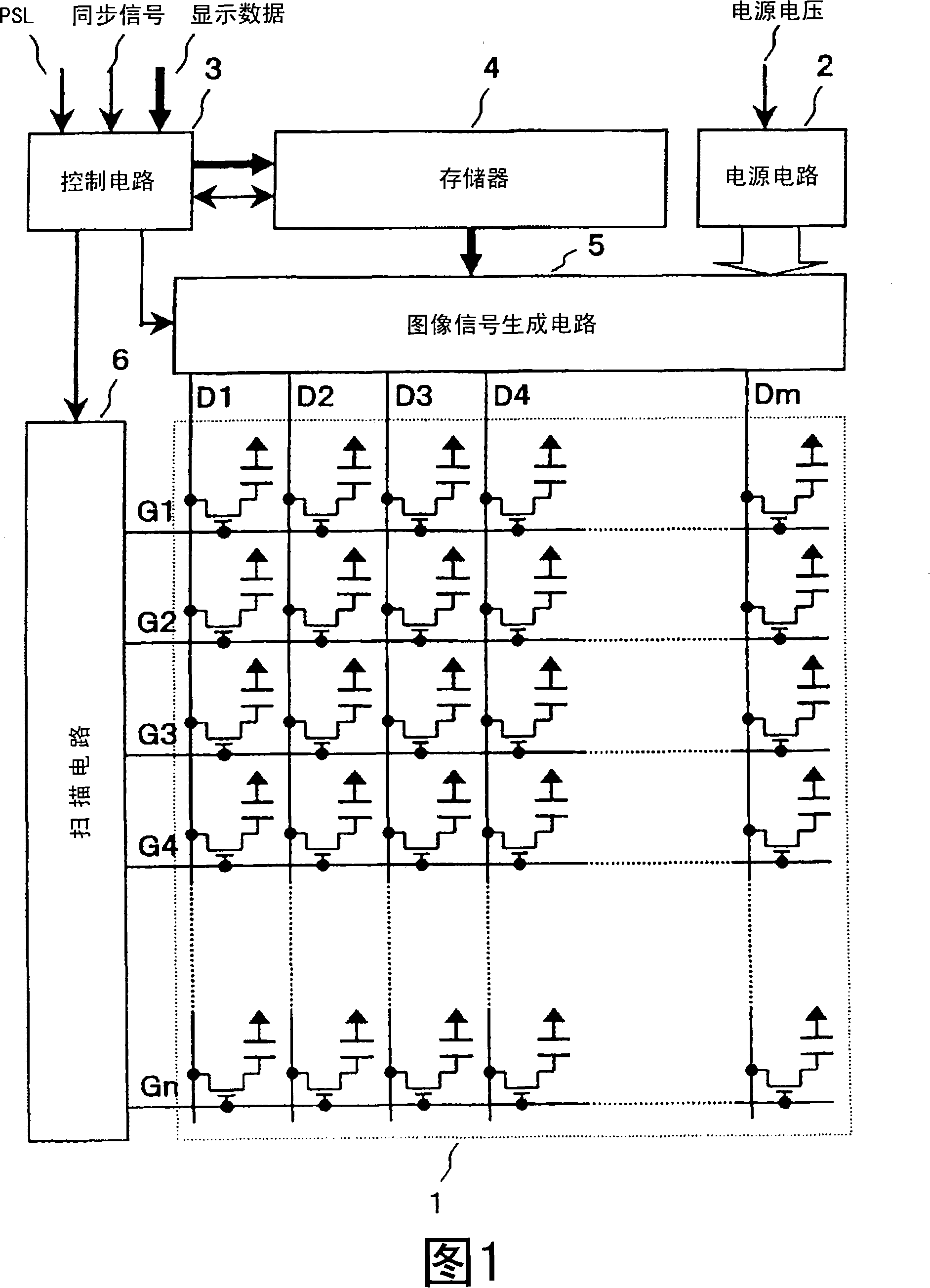
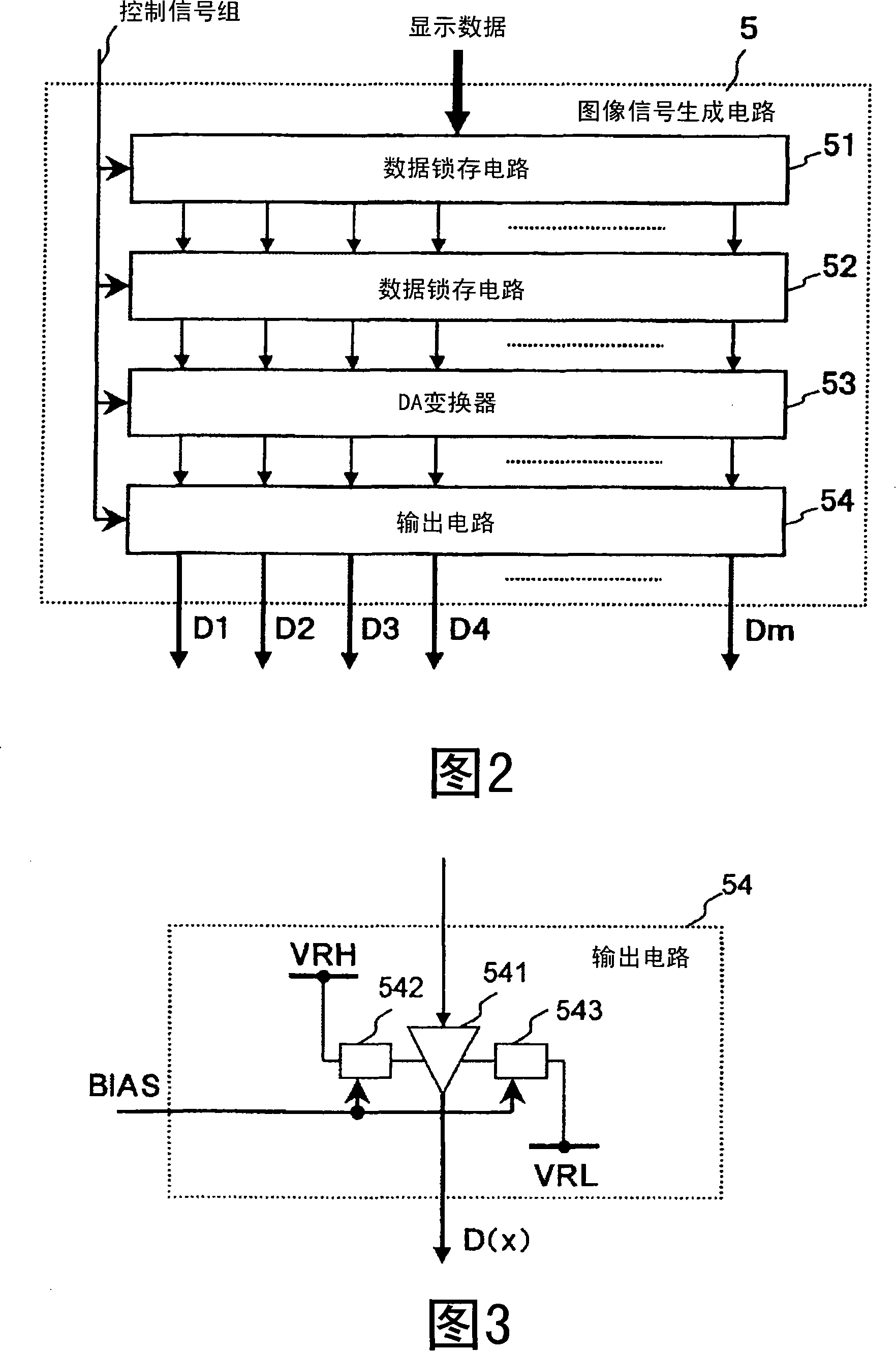
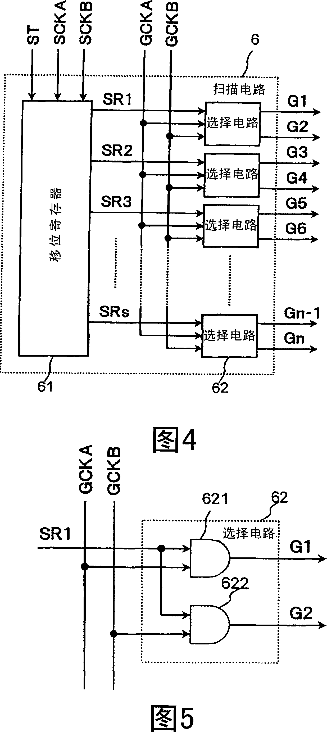
[0052] FIG. 1 is a structural diagram of a display device according to Embodiment 1 of the present invention. In Fig. 1, 1 is a display panel in which a plurality of pixels are arranged in a matrix shape; 2 is a power supply circuit for generating grayscale voltages necessary for display from a power supply voltage; 3 is input of PSL signals, Synchronous signal and other control signals or setting values ​​and display data, control circuit for generating and outputting control...

Embodiment 3

[0097] FIG. 16 is a structural diagram of a display device of the present invention. In FIG. 16, the input signal INPUT_SIG and the control signal REG are input into the signal voltage generation circuit 11 from the outside, and the signal voltage generation circuit 11 generates and applies the signal line SIGn (n=1 to N, N is an integer) according to the input signal INPUT_SIG. signal voltage. Furthermore, the signal voltage generating circuit 11 generates an AC signal M to be supplied to the common scanning circuit 12 based on the input control signal REG.

[0098] Also, the signal voltage generating circuit 11 generates the scanning signal SFT_ST supplied to the common scanning circuit 12 and the gate scanning circuit 13 according to the synchronization signal in the input signal INPUT_SIG, and generates the high-level common voltage VCOMH and the low-level common voltage supplied to the common scanning circuit 12 . level common voltage VCOML.

[0099] The common scanning...


PUM


Abstract

A display panel is scanned every two lines during a period of binary writing area in the first half of one frame period in partial display (or in small gradation display) and a steady-state current of an output amplifier for buffering gradation signals supplied to the display panel in a non-scanning period in the second half of one frame period is reduced.

Description

[0001] This application is based on, and claims the benefit of priority from, Japanese Priority Patent Application No. 2007-010952 filed on January 22, 2007 and Japanese Priority Patent Application No. 2007-011740, filed on January 22, 2007, the latter applications being incorporated by reference All methods are incorporated into this application. technical field [0002] The present invention relates to a display device and a driving method thereof with a multi-grayscale display mode and a few grayscale display mode (the number of grayscale levels is less than that of the multi-grayscale display mode), and in particular to a liquid crystal display, an organic EL display, and a plasma display , Field emission display and its driving method. [0003] Furthermore, the present invention relates to a display device in which power consumption during partial display is reduced. Background technique [0004] U.S. Patent Laid-Open 2005 / 0179677 (Japanese Patent Application Laid-Open...

Claims


Application Information

Patent Timeline
Patent Type & Authority Applications(China)
IPC IPC(8): G09G3/20G09G3/36
Inventor 万场则夫古桥勉
Owner JAPAN DISPLAY INC
Why Eureka
Try Eureka