Multiple output power supply

A multi-channel output and power supply technology, which is applied in the direction of output power conversion device, DC power input conversion to DC power output, electrical components, etc., can solve the problem of high transformer temperature, failure to pass safety regulations, overheating of wiring, and power supply duty cycle. Large and other problems, to achieve the effect of improving electromagnetic compatibility characteristics, preventing excessive temperature, and simple circuit

Active Publication Date: 2008-07-30
VERTIV CORP
View PDF0 Cites 28 Cited by
  • Summary
  • Abstract
  • Description
  • Claims
  • Application Information

AI Technical Summary

Problems solved by technology

[0008] When we use the output voltage of an auxiliary circuit that detects multiple outputs for protection, since there may be output circuits with small currents in other auxiliary circuits, when there is a short circuit or overcurrent, the output overcurrent or short circuit current will be caused by the presence of large line resistance and internal resistance. Insufficient to maximize the duty cycle of the power supply, and the transformer cannot pass safety regulations or have safety problems due to the high temperature of this winding, or the existence of other safety problems caused by overheating of PCB traces
[0009] When the input voltage range is wide, the duty cycle of all outputs with the lowest input voltage at full load is greater than the duty cycle of one output in over-current or short-circuit state when the input voltage is higher, and the other output circuits are in light load, using the method of voltage detection can not correctly detect the output overcurrent or short circuit fault

Method used


Image

  • Multiple output power supply
  • Multiple output power supply
  • Multiple output power supply

Examples


specific Embodiment approach 1

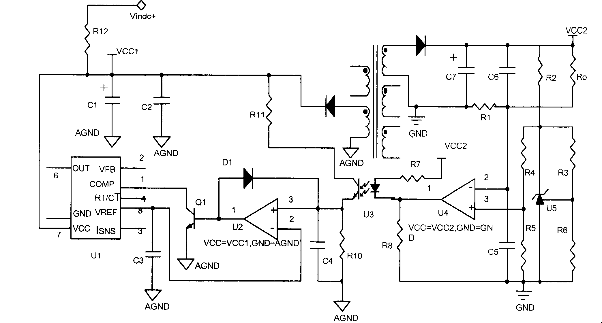
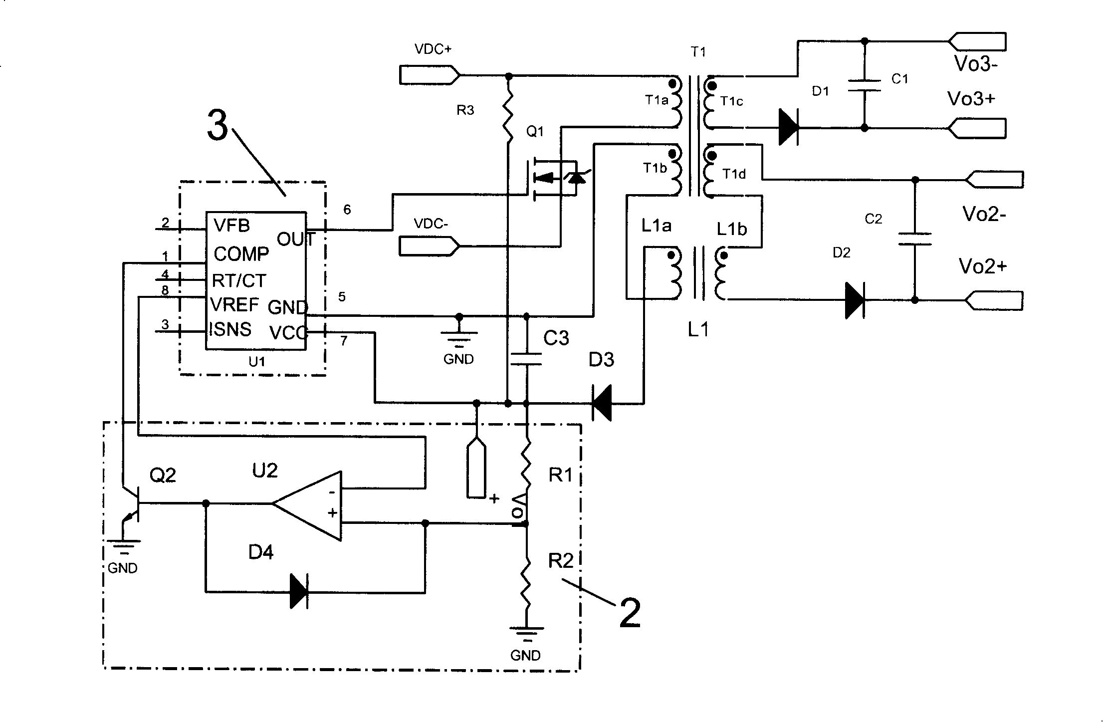
[0037] Such as figure 2 The shown single-ended flyback three-way output power supply includes a transformer T1 , a voltage detection and comparison module 2 , and a power control module 3 . The transformer T1 has four windings, namely the first primary winding T1a, the second primary winding T1b, the first secondary winding T1c and the second secondary winding T1d. Among them, the first primary winding T1a corresponds to the input of the transformer T1, the second primary winding T1b, the first secondary winding T1c and the second secondary winding T1d correspond to the three outputs of the transformer T1, namely Vo1, Vo2 and Vo3 Road. The Vo1 output is also connected to the voltage detection and comparison module 2 as an output overcurrent or short circuit detection circuit. The Vo2 output is a small current output, that is, its rated load current is small; the Vo3 is a main output with feedback (not shown in the figure).

[0038] The switch tube Q1 is connected between t...

specific Embodiment approach 2

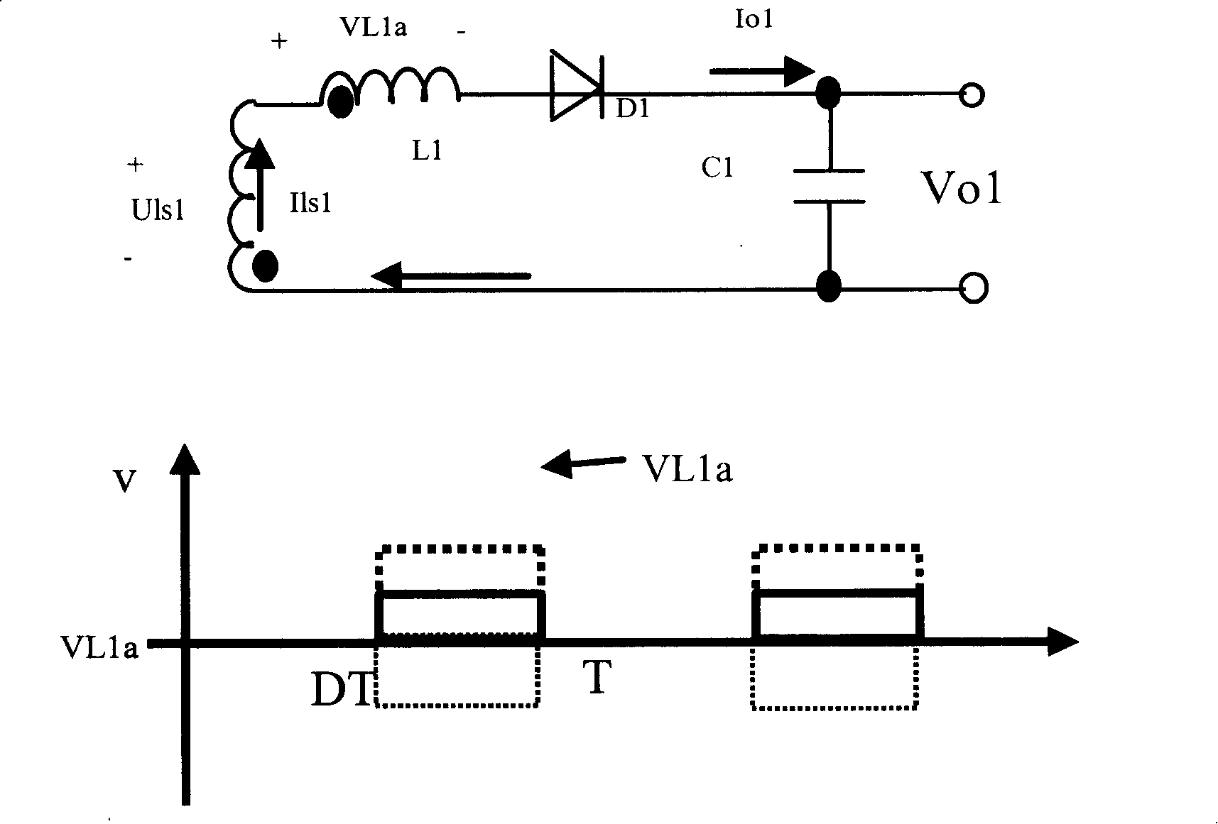
[0066] Such as Figure 7 As shown, the difference between this specific embodiment and the first specific embodiment is that: the inductor L1 has three windings, namely the first winding L1a, the second winding L1b and the third winding L1c. The first winding L1a is connected in series on the detection output path, and the second winding L1b and the third winding L1c are respectively connected in series on the small current output path (the main output path is not shown in the figure). The current flow direction of the second winding L1b and the third winding L1c is opposite to that of the first winding L1a.

[0067] This enables directional over-current or short-circuit protection of the two low-current outputs. Apparently, windings can also be added to more than two small current output circuits, and overcurrent or short circuit protection for more than two small current output circuits has been formed.

specific Embodiment approach 3

[0068] Such as Figure 8 As shown, the difference between this specific embodiment and the first specific embodiment is that: the inductor L1 has three windings, namely the first winding L1a, the second winding L1b and the third winding L1c. The first winding L1a is connected in series on the detection output path, and the second winding L1b and the third winding L1c are connected in series on the small current output path and the main output path respectively. The current flow direction of the second winding L1b and the third winding L1c is opposite to that of the first winding L1a.

[0069] Due to the negative feedback of the main circuit, when a winding of the inductor is added to the main circuit, the added inductance will cause the voltage of the main circuit to drop when the main circuit is overcurrent. Due to the closed-loop negative feedback, the duty cycle of the power supply will increase to maintain the main circuit The output of the detection circuit is stable, bu...


PUM


Abstract

The invention discloses a multiple output supply, comprising a transformer provided with at least two output paths, a power control module for controlling the input of the transformer, and a voltage detecting comparison module. The voltage detecting comparison module detects an output voltage of a certain output path in a plurality of output paths except a main output path provided with feedback, and outputs the detecting result to the power control module; the power control module can start up the protection according to the detecting result. The invention further comprises a mutual-inductance element, wherein the mutual-inductance element is in series connected to a detecting output path which is connected with a voltage detecting module and at least one output path of the multiple output supply respectively. The circuit of the invention is very simple, complicated circuits, such as reference source and comparator, are not needed, and the parts that can bring depletion such as resistance are not required.

Description

technical field [0001] The invention relates to a power supply circuit, in particular to a multi-channel output power supply. Background technique [0002] At present, in the multi-output power supplies used in the industry, the main circuit is the output circuit with negative feedback, which has relatively stable performance and high voltage regulation accuracy, while the other output circuits without feedback have poor performance and low voltage regulation accuracy. , so the output with the largest current or the highest importance is generally used as the main output. The remaining small current output circuits are used as auxiliary circuits. At present, the industry's requirements for safety regulations are becoming more and more formal. Each output of a multi-output power supply generally needs to be tested for overload and short circuit. Thin, the wire resistance will be larger, and the PCB trace of the output circuit is generally thinner, and the wire resistance wi...

Claims


Application Information

Patent Timeline
Patent Type & Authority Applications(China)
IPC IPC(8): H02M3/00H02H7/10H02H3/08H02M1/14H01F27/28
Inventor 吴连日
Owner VERTIV CORP
Why Eureka
Try Eureka