Hybrid drive device

A driving device and hybrid technology, applied in power devices, electric power devices, hybrid vehicles, etc., can solve the problems of inability to continuously change the engine speed, inability to increase the input speed, poor fuel efficiency, etc.

Active Publication Date: 2008-07-30
AISIN AW CO LTD +1
View PDF2 Cites 21 Cited by
  • Summary
  • Abstract
  • Description
  • Claims
  • Application Information

AI Technical Summary

Problems solved by technology

However, in the technology disclosed in this document, since the input rotation speed cannot be increased on the transmission side, and the rotation speed of the engine cannot be continuously changed in this state, the engine cannot be operated through the optimal fuel efficiency line, and the fuel efficiency is poor.

Method used


Image

  • Hybrid drive device
  • Hybrid drive device
  • Hybrid drive device

Examples


no. 1 approach

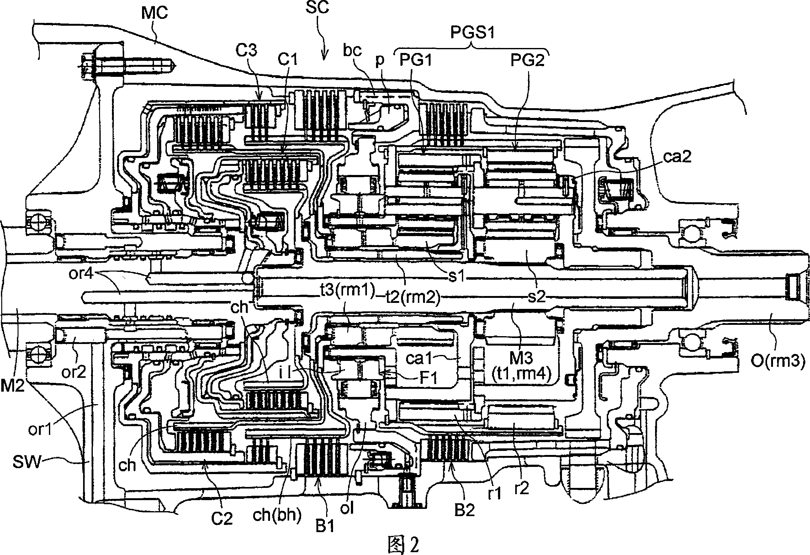
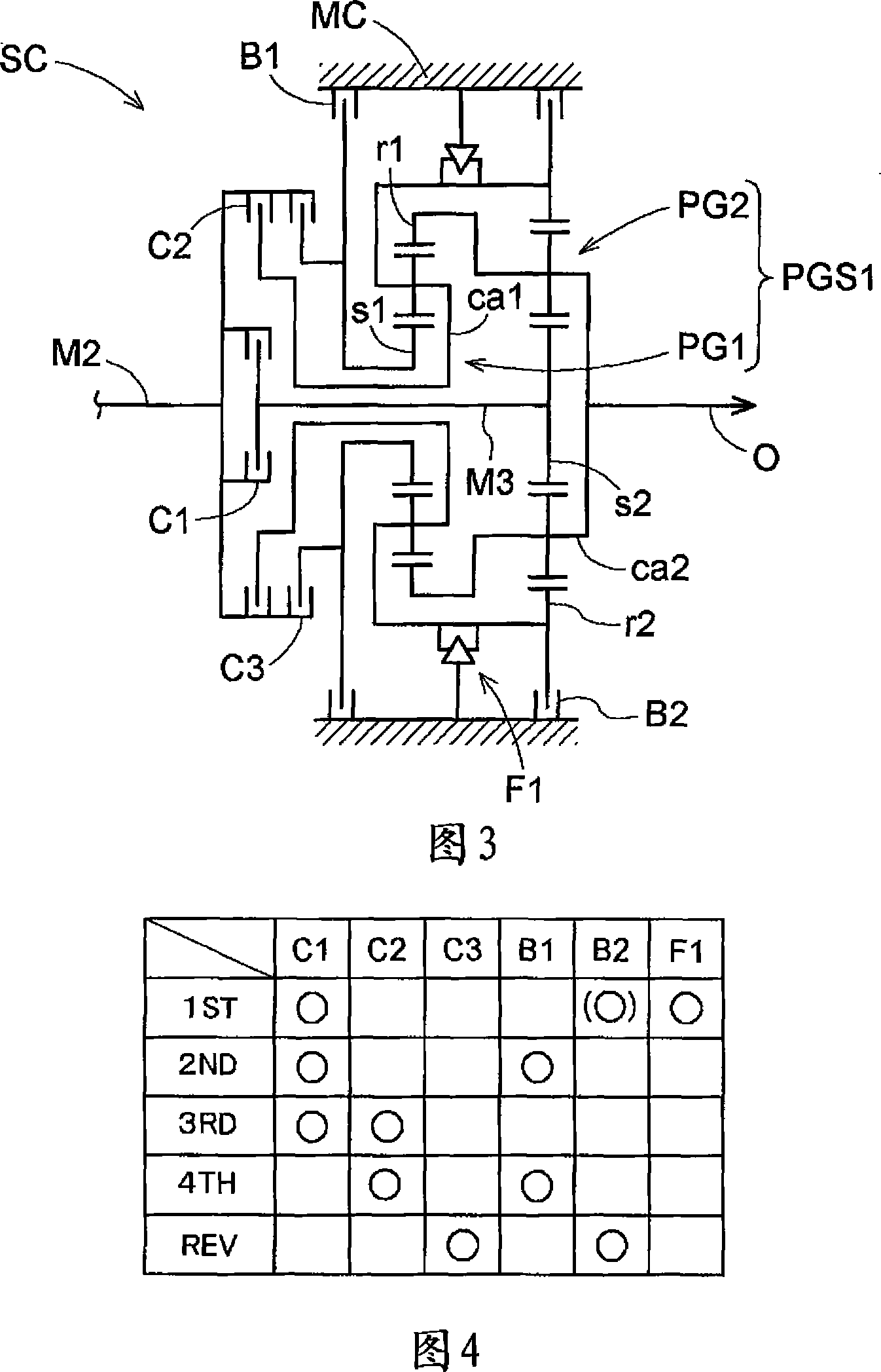
[0145] FIG. 2 shows a specific configuration of the rear of the transmission of this embodiment, and FIG. 3 shows a schematic diagram.

[0146] As can be seen from these figures, the transmission SC is configured to include a planetary gear set PGS1 composed of a pair of single planetary gears PG1 and PG2, and has a plurality of friction engagement elements C1 and C2 corresponding to the rotation elements constituting the planetary gear set PGS1. , C3, B1, B2, F1.

[0147] As friction engagement elements, a first clutch C1, a second clutch C2, and a third clutch C3, a first brake B1, and a second brake B2 are provided, and a one-way clutch F1 is provided. FIG. 4 shows an operation table of these frictional engagement elements.

[0148] drive transmission

[0149] Based on Fig. 3 as a skeleton diagram, Fig. 4 as an operation table of frictional engagement elements, the diagram on the right side of Fig. 5 as a speed diagram, Fig. 6 showing the driving transmission state of eac...

no. 2 approach

[0194] FIG. 8 shows the specific structure of the rear end of the transmission SC in this embodiment, and FIG. 9 shows its skeleton diagram. The difference between this embodiment and the first embodiment will be described. In the first embodiment, the first clutch C1 is disposed between the second electric motor MG2 and the planetary gear set PGS1 . A clutch C1 is arranged on the output shaft O side of the planetary gear set PGS2.

[0195] In this example, the second intermediate shaft M2 and the third intermediate shaft M3 are coupled to rotate integrally by a spline shaft. In addition, the output from the carrier ca2 of the second planetary gear PG2 is transmitted to the output shaft O via the output drum OD and the fourth intermediate shaft M4 rotatably provided integrally therewith.

[0196] Therefore, the skeleton diagram becomes as shown in FIG. 9 , and the operation table of the friction engagement element is the same as the table shown in FIG. 4 . In addition, the v...

no. 3 approach

[0208] Based on FIG. 10 which is a skeleton diagram of the third embodiment, FIG. 4 which is a friction engagement element operation table, and FIG. 11 which is a velocity diagram, first, the drive transmission of this embodiment will be described.

[0209] In this embodiment, when the pair of planetary gears PG constituting the planetary gear set PGS3 serving as the planetary gear set for shifting is also referred to as the first gear in order from the second intermediate shaft M2 serving as the input member of the transmission SC toward the output shaft O, When the planetary gear PG1 and the second planetary gear PG2 are used, these planetary gears are single planetary gears respectively provided with sun gears s1 , s2 , carriers ca1 , ca2 , and ring gears r1 , r2 .

[0210] When describing the relationship with the frictional engagement coefficient, the following structure is adopted, that is, the ring gear r1 of the first planetary gear PG1 is selectively fixed to the trans...


PUM


Abstract

The present invention provides a hybrid driving device adopting a dual-motor separation method, which can ensure acceleration performance in a low-speed range and has high fuel efficiency in a high-speed range. An input shaft drivingly connected to the engine, an output shaft drivingly connected to the wheels, a first electric motor and a second electric motor are provided, and planetary gears for power distribution constituting the first, second, and third rotation elements in the order of rotation speed are provided, wherein The first electric motor is connected to the first rotating element, the input shaft is connected to the second rotating element, the intermediate transmission shaft and the second electric motor are connected to the third rotating element, and a transmission is provided, which has a plurality of shifting stages and will be transmitted from the intermediate transmission shaft The power from the transmission is output to the output shaft. The multiple shift stages of the transmission include at least an increase shift stage and a deceleration shift stage. , there is a partition through which the intermediate drive shaft passes.

Description

technical field [0001] The present invention relates to a hybrid driving device, which comprises an input shaft drivingly connected to an engine, an output shaft drivingly connected to a wheel, a first electric motor and a second electric motor, and first, second, and third motors in order of rotation speed. A planetary gear for power distribution of three rotating elements, the planetary gear connects the first electric motor to the first rotating element, connects the input shaft to the second rotating element, and connects the intermediate transmission shaft and the second electric motor to the first rotating element. The three rotation elements are connected; and a transmission is provided, which has a plurality of shift stages, and outputs the power transmitted from the intermediate transmission shaft to the output shaft. Background technique [0002] This type of hybrid drive device, as disclosed in Patent Document 1, includes a first electric motor, a planetary gear f...

Claims


Application Information

Patent Timeline
Patent Type & Authority Applications(China)
IPC IPC(8): B60K6/20B60K17/04B60L11/14F16H3/62F16H3/66B60K6/365B60K6/445B60K6/547B60L50/15B60L50/16B60W10/08B60W10/10B60W20/00F16H59/14F16H59/42F16H61/04F16H61/68F16H61/684F16H61/686F16H63/40F16H63/50
CPCB60K1/02B60K6/365B60K6/445B60K6/547B60L2240/421B60L2240/423B60L2240/441B60L2240/486B60W10/08B60W10/115B60W20/00B60W30/19B60W2510/0638B60W2510/081B60W2510/104B60W2710/083F16H3/728F16H2037/0873F16H2200/0043F16H2200/201F16H2200/2046F16H3/66F16H2200/2007B60L50/61B60L50/16Y02T10/62Y02T10/64Y02T10/7072Y02T10/70B60W20/15
Inventor 高见重树新智夫矢田裕贵岩中诚柿并拓马北条康夫小嶋昌洋茨木隆次田端淳岩濑雄二松原亨柴田宽之
Owner AISIN AW CO LTD
Why Eureka
Try Eureka